background image

52

63138-US-200110

1.

Open and remove padlock.

2.

The radiation safety officer gets a separate notification with the code for 
the padlock. Contact your sales organization.

3.

Keep the padlock near by the source holder. Do not insert the  padlock into 
the opening of the "OFF" position or you cannot switch the source holder 
off completely in case of emergency.

4.

Screw out safety screw (3) (screw is fixed to the safeguard cable and is 
not detachable.

5.

Turn the operating lever 90° clockwise up to the stop. "ON" (1) then 
appears in the position recess of the operating lever.

6.

Secure the operating lever in position "ON" (1).

7.

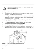
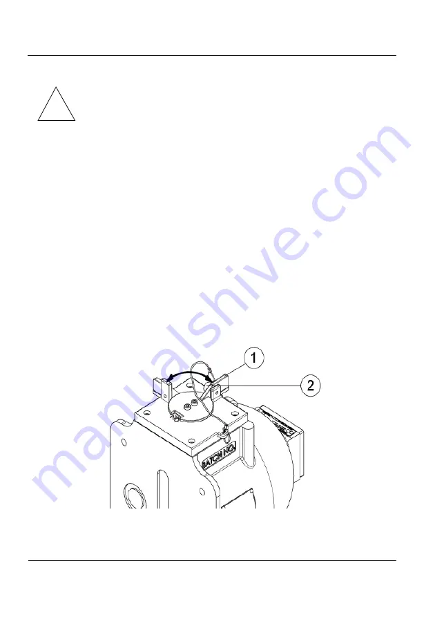
Screw in the safety screws (3) as shown in Figure 6.2. Vibrations or other 
external influences can cause uncontrolled movement of the operating lever.

Figure 6.2

Safety Screws for Secure Switching Position

1. Operating lever in switching position "ON"
2. Safety screw

Make sure the source holder shutter is in the “OFF” position before 
switching the radiation on.

!

NOTE

Summary of Contents for SHLD 2

Page 1: ...Operating Instructions SHLD 2 Source Holder Document ID 63138 Radiometric...

Page 2: ......

Page 3: ...ppropriate Use 12 Incorrect Use 12 Safety Instructions 12 Installation and Operation in US Canada 13 Safety Instructions for Ex Areas 13 Applications 14 Intended Applications 14 Certifications 14 Stan...

Page 4: ...27 Mass Flow Orientation 28 Point Level Orientation 29 Density Orientation 30 Vertical Pipeline 30 Inclined diameter 1 97 3 94 in 50 100 mm 31 Vertical Pipeline diameter 1 97 23 62 in 50 600 mm 32 Av...

Page 5: ...ditions 46 Radiation Fields Inside Vessels 46 Pneumatic Switching Facility Connection 47 Potential Equalization 47 Connection Cable 47 Electrical Connection 48 Compressed Air Connection 49 Connecting...

Page 6: ...or Removal Requirements 63 Transfer Ownership or Disposal 65 Source Disposal 65 9 Supplemental Information 67 Technical Data 67 General Data 67 Materials 68 Pneumatic Switching Mechanism optional 75...

Page 7: ...e expressed written permission of VEGA Americas Inc The material in this document is provided for informational purposes and is subject to change without notice ISO 9001 2015 approval by Eagle Registr...

Page 8: ...6 63138 US 200110 NOTES...

Page 9: ...documentation are designed for users seeking product knowledge usage and functionality Make certain you read and understand this information before putting the instrument into operation Figure 1 1 SHL...

Page 10: ...ician Field Service Internal Support Process Engineers Field Sales 1 3 Explanation of Symbols Danger Identifies an imminently hazardous situation which if not avoided will result in death or injury Wa...

Page 11: ...tructions for Ex applications Radiation Introduces information concerning radioactive materials or radiation safety Bulleted list Indicates a list of items with no intended or implied sequence 1 Steps...

Page 12: ...10 63138 US 200110 NOTES...

Page 13: ...quirements regulations and restrictions with respect to the use of radiometric instrumentation You are responsible for familiarizing yourself with your national and local regulations These regulations...

Page 14: ...n protection regulations during installation and operation Operational reliability is ensured only if the instrument is used properly VEGA is not liable for damages caused by improper use 2 4 Incorrec...

Page 15: ...ply with the relevant requirements of the National Electrical Code ANSI NFPA 70 Installations in Canada shall comply with the relevant requirements of the Canadian Electrical Code 2 7 Safety Instructi...

Page 16: ...g 2 9 Certifications These source holders are designed for certification compliance from the following agencies AERB India B C and R only CNSC Canada ODH NRC Ohio Department of Health and Nuclear Regu...

Page 17: ...source against mechanical damage or chemical influences In case of large measuring ranges such as high vessels two or more source holders are used 3 2 Components The SHLD 2 houses a source capsule tha...

Page 18: ...ted in stainless steel Optional Special Form triple encapsulated in Haynes 320 Shutter A shutter is the mechanism that opens or closes the radiation beam port and either permits or denies the movement...

Page 19: ...igure 3 1 Position of the Type Labels 1 Type Label Source 2 Type Label Source Holder 3 Warning U S optional The local dose rate on the type label at a defined distance is safety oriented and includes...

Page 20: ...rce Cs 137 2 Serial Number of Source Capsule for traceability of source 3 Activity of Sources in MBq and mCi or GBq and mCi 4 Date dd mm yyyy U S Version mm yy 5 Number of Corresponding Operating Inst...

Page 21: ...tions Apart from the manual versions there are also versions with pneumatic switchover Figure 3 3 SHLD 2 Versions 1 Overview 2 Standard Version 3 With Position Switch 4 With Interlock Safety Switch 5...

Page 22: ...veyor belt spiral conveyor directly opposite the sensor The source container shields the environment against gamma radiation and protects the radioactive source against mechanical damage or chemical i...

Page 23: ...oam packaging As an option the source holder can be also shipped in a wooden box USA For transport in Europe the source holder is protected in an outer packaging of sheet steel The outer packaging of...

Page 24: ...4 File a claim against the carrier reporting the damage in detail if there was damage to the unit during shipment Any claims against VEGA for shortages errors in shipment etc must occur within 30 day...

Page 25: ...older immediately find a storage area that is secure and isolated 8 Allow access to authorized personnel only 9 Maintain records of the shipping and receipt 10 While they are not required a survey and...

Page 26: ...24 63138 US 200110 NOTES...

Page 27: ...ingsorcontactVEGA Americas 5 Ensure adequate clearance to operate the shutter or cable mechanism 6 Consider in advance any high temperature or corrosive environmental conditions For example you should...

Page 28: ...ple by taking suitable measures such as a safety fence when mounting the source holder Depending on the version the center of gravity of the SHLD 2 can vary Keep this in mind during crane transport on...

Page 29: ...ted exactly towards the detector mounted on the opposite side The source holder SHLD 2 should be mounted as close as possible to the vessel However with large measuring ranges and small vessel diamete...

Page 30: ...the source holders depends on the width and the loading height of the conveyor belt In the case of wide conveyor belts using two sources holders is advantageous Make sure that the total width of the c...

Page 31: ...horizontal you have to mount the source holder so that the implied opening of the exit channel is in a horizontal position Mount the SHLD 2 as close as possible to the vessel With large measuring rang...

Page 32: ...essories in the chapter Supplemental Info Mount the source holder SHLD 2 as close as possible to the vessel However with large measuring ranges and small vessel diameters a gap can often is not avoida...

Page 33: ...l radiation path is recommended The distance of the beam through the medium is thus longer and an improved measuring effect is achieved In such cases the optional lead shielding for the detector is re...

Page 34: ...n 50 600 mm a straight radiation path is possible Mount the radiometric sensor either horizontally or vertically Figure 4 5 Vertical Pipeline 30 diameter 1 97 23 62 in 50 600 mm 1 Source Holder SHLD 2...

Page 35: ...sensor horizontally the optional lead shielding is recommended in order to avoid influence from secondary radiation sources Figure 4 6 Vertical Pipeline with Horizontal Sensor 1 97 23 62 in 50 600 mm...

Page 36: ...pipeline On a horizontal pipeline the radiation should be directed horizontally to avoid interference from air pockets Figure 4 7 Measurement Setup on Horizontal Pipeline 1 Source holder SHLD 2 2 Radi...

Page 37: ...ied lock washers to the following illustration Use the prescribed torque for the mounting screws M10 Make sure that the screws have electrical contact to the potential equalization Figure 4 8 Lock Was...

Page 38: ...Dose Rate After mounting or as soon as the radioactive emitter is mounted in the source holder you must measure the local dose rate in the area of the source holder and the detector Depending on the r...

Page 39: ...n of the equipment has changed or is different from the original order notify VEGA before installing the equipment External Obstructions Any material in the path of the radiation can affect the measur...

Page 40: ...ng them on adjacent vessels Make sure to maintain the appropriate source to detector distance as illustrated in Figure 4 10 Figure 4 10 Source Detector Arrangement for Adjacent Vessels 1 Radiation Bea...

Page 41: ...ic switching shutter operates from 12 C 105 C 10 F 221 F Shipping Shield The source holder is transported with a shield in place for protection and shielding This shield is installed on the flange end...

Page 42: ...40 63138 US 200110 NOTES...

Page 43: ...costs use this checklist to ensure the gauge is ready for commissioning before the engineer arrives Allow access to the source holder for testing purposes Have process ready for adjustment Toensure th...

Page 44: ...relocation as a new installation Installation is the process of preparing the mounted source holder for use and consists of the following Preliminary radiation survey Leak test Installation radiation...

Page 45: ...erial number or other identification on the bag 3 Open the zip top bag and grasp the swab stick by the end opposite of the fiber tip 4 Wipe the external surface of the source holder by using the fiber...

Page 46: ...des anyone whose assigned duties require his presence in the vicinity of the source holder Complete the evaluation to determine if the limit of 50 000 mSv 5 000 mrem per year which would require monit...

Page 47: ...n levels by level detectors or other means is necessary to ensure that the source is in the shielded position and not in the source well Keep the records of these tests listing the date and name of th...

Page 48: ...umentation consistent with OSHA rules At a minimum follow the steps listed below where applicable 1 Verify by signature that the source holder is locked in the OFF shutter closed position 2 Ensure tha...

Page 49: ...on regulations As a rule connect the SHLD 2 to vessel ground PA or in case of plastic vessels to the next ground available Inside the housing there is a ground terminal On the outside of the lower hou...

Page 50: ...tion Terminal Box of Position Switches 1 Upper position switch for switch position ON terminals 1 to 3 2 Lower position switch for switch position OFF terminals 4 to 6 3 Ground terminal 4 Connection t...

Page 51: ...d Tighten the pneumatic line and make sure there are no leaks in the entire air line In case of a leak the pneumatic switching mechanism switches automatically to the OFF position spring pressure as s...

Page 52: ...follows 1 Remove the padlock 2 Pull out the locking bolt These steps secure the OFF position The locking bolt is fixed on a steel cable 3 Using compressed air switch the pneumatic actuator from the O...

Page 53: ...lds the environment against gamma radiation and protects the radioactive source against mechanical damage or chemical influences Switching on Radiation Figure 6 1 Switching on Radiation with Manual Op...

Page 54: ...w is fixed to the safeguard cable and is not detachable 5 Turn the operating lever 90 clockwise up to the stop ON 1 then appears in the position recess of the operating lever 6 Secure the operating le...

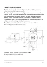
Page 55: ...rdous area The requirements on function and design of the safety switch are extremely different making it impossible to mount a certain switch version in advance For that reason there is only a mounti...

Page 56: ...54 63138 US 200110 NOTES...

Page 57: ...with pneumatic switching mechanism with water and a slightly damp rag Avoid creating electrostatic charges on the instrument Never rub the source holder with a dry cloth when cleaning 7 2 Inspection...

Page 58: ...nd carrying out this test every six months See the Shutter ON OFF Mechanism procedure Manual Shutter Mechanism To test the function of the shutter mechanism on a manual shutter complete the following...

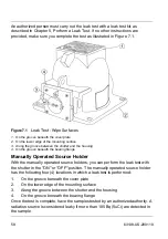
Page 59: ...ielding as noted by the specifications of the handling permit Specifically you must perform a leak test for the following reasons Regular testing during operation When the source holder is stored for...

Page 60: ...neath the bearing flange Manually Operated Source Holder With the manually operated source holders you can perform the leak test with the shutter in the ON or OFF position The manually operated source...

Page 61: ...licable source holders Every six months unless otherwise required by applicable nuclear regulatory agency See the Shutter ON OFF Mechanism procedure Source wipe Leak test Every three years unless othe...

Page 62: ...the following General cleanliness Annually Make certain there is no buildup of dirt or process material on the source holder Corrosion or rusting Annually Check the housing winches and the shutter loc...

Page 63: ...or is assumed to exist Cable not operating correctly Contact VEGA Americas Nuclear Services Source leak Evacuate the immediate area and control entry to the area Contact VEGA Americas Nuclear Services...

Page 64: ...rce holder The emergency procedure protects personnel until the responsible radiation safety officer arrives and decides upon further measures The person charged with the supervision of the radiation...

Page 65: ...remove the source holder perform the following steps Conduct a visual inspection of source holder Make certain the external surface is smooth and not damaged Check corroded and rusted units which have...

Page 66: ...it Only a specifically licensed individual can perform the removal The specifically licensed person must use a calibrated survey meter Make sure the radiation safety officer is present at the site dur...

Page 67: ...tion regarding the disposal of the source The contact information for the U S and Canada is Contact Information Telephone Number Monday through Friday 8 00 A M 5 00 P M EST Eastern Standard Time 1 844...

Page 68: ...66 63138 US 200110 NOTES...

Page 69: ...tes Temperature Manual Shutter Pneumatic Shutter 50 C 105 C 58 F 221 F 12 C 105 C 10 F 221 F Pressure Atmospheric Humidity 0 100 non condensing Weight Manual Shutter Pneumatic Shutter Pneumatic Shutte...

Page 70: ...3701 1 46 an equivalent to 10 CFR 31 and 32 If you need to transfer the source holder to another location or dispose of the source holder specific licensees are required Handling Installation and Stor...

Page 71: ...Component Material 1 Type Label Source 316 2 Cover Plate 316 O ring beneath cover plate FKM 3 Housing 316 4 Bearing Flange 316 5 Shutter Handle 316 6 Screw 316 7 Safeguard Cable 304 Plastic coated Vin...

Page 72: ...abel Source 316 2 Cover Plate 316 O ring beneath cover plate FKM 3 Housing 316 4 Mounting Plate 316 5 Housing Limit Switch Zinc Die Casting 6 Shutter Limit Switch 304 7 Screw 316 8 Shutter Handle 316...

Page 73: ...ce 316 2 Cover Plate 316 O ring beneath cover plate FKM 3 Housing 316 4 Mounting Plate 316 5 Housing Safety Switch with Locking Rod Lock provided by customer 6 Screw 316 7 Shutter Handle with Interloc...

Page 74: ...ring FKM 3 Housing 316 4 Bearing Flange 316 5 Screw 316 6 Locking Rod 316 7 Bracket Air Actuator 316 8 Housing Air Actuator Aluminum Anodized 9 Screw 316 10 Screw 304 11 Indication of Switching Posit...

Page 75: ...ing 316 4 Bearing Flange 316 5 Screw 316 6 Locking Rod 316 7 Bracket Air Actuator 316 8 Housing Air Actuator Aluminum Anodized 9 Screw 316 10 Screw 304 11 Indication of Switching Position Polycarbonat...

Page 76: ...erial 1 Type Label Source 316 2 Cover Plate 316 O Ring FKM 3 Housing 316 4 Bearing Flange 316 5 Screw 316 6 Bracket Exp Proof Limit Switch 316 7 Limit Switch Exp Proof Zinc Die Casting 8 Shutter Handl...

Page 77: ...cility By spring force Compressed air conditioning Class 5 according to ISO 8573 1 pressure dew point 10 K below operating temperature See local regulations for International regulations Connection da...

Page 78: ...76 63138 US 200110 9 2 Dimensions Figure 9 7 Source Holder SHLD 2 Standard Version...

Page 79: ...63138 US 200110 77 Figure 9 8 SHLD 2 Beam Angles Figure 9 9 SHLD 2 Height for Source Exchange...

Page 80: ...78 63138 US 200110 Figure 9 10 Source Holder SHLD 2 with Limit Switch...

Page 81: ...63138 US 200110 79 Figure 9 11 Source Holder SHLD 2 with Interlock Safety Switch...

Page 82: ...80 63138 US 200110 Figure 9 12 Source Holder SHLD 2 with Air Actuator...

Page 83: ...63138 US 200110 81 Figure 9 13 Source Holder SHLD 2 with Air Actuator and Limit Switch...

Page 84: ...82 63138 US 200110 Figure 9 14 Source Holder SHLD 2 Explosion Proof with Limit Switch...

Page 85: ...rial 10 2 U S Canada and Worldwide VEGA has Field Service Engineers available for on site service emergency services or gauge start up 10 3 Necessary Information When you call with a question please h...

Page 86: ...84 63138 US 200110 NOTES...

Page 87: ......

Page 88: ...a com www vega americas com 63138 US 200110 Subject to change without prior notice 2020 VEGA Americas Inc Cincinnati Ohio USA All statements concerning scope of delivery application practical use and...

Reviews: