background image

D

epending on the reason for the fault and the measures taken

,

the

steps described in chapter

"

S

et up

"

may have to be carried out again

.

7

.

3

I

nstrument repair

I

f a repair is necessary

,

please proceed as follows

:

Y

ou can download a return form

(

23

KB

)

from our

I

nternet homepage

www

.

vega

.

com under

:

"

D

ownloads

-

F

orms and certi

cates

-

R

epair

form

"

.

B

y doing this you help us carry out the repair quickly and without

having to call back for needed information

.

l

P

rint and

ll out one form per instrument

l

C

lean the instrument and pack it damage

-

proof

l

A

ttach the completed form and

,

if need be

,

also a safety data

sheet outside on the packaging

l

P

lease ask the agency serving you for the address of your return

shipment

.

Y

ou can

nd the respective contact data on our website

www

.

vega

.

com under

:

"

C

ompany

-

VEGA

worldwide

"

R

eaction after fault rec

-

ti

cation

22

VEGABAR

17

7

M

aintenance and fault recti

cation

27636

-

EN

-

120531

Summary of Contents for VEGABAR 17

Page 1: ...Operating Instructions VEGABAR 17 Document ID 27636 Process pressure ...

Page 2: ...cription 3 1 Structure 7 3 2 Principle of operation 8 3 3 Operation 8 3 4 Packaging transport and storage 8 4 Mounting 4 1 General instructions 10 4 2 Instructions for installation 10 4 3 Mounting steps 10 5 Connecting to power supply 5 1 Preparing the connection 12 5 2 Connection procedure 13 5 3 Wiring plan 16 6 Setup 6 1 Setup steps 18 6 2 Recalibration 18 7 Maintenance and fault rectification 7...

Page 3: ...entation Information Supplementary documents appropriate to the ordered version come with the delivery You can find them listed in chapter Product description Editing status 2012 05 29 VEGABAR 17 3 Contents 27636 EN 120531 ...

Page 4: ...formation tip note This symbol indicates helpful additional information Caution If this warning is ignored faults or malfunctions can result Warning If this warning is ignored injury to persons and or serious damage to the instrument can result Danger If this warning is ignored serious injury to persons and or destruction of the instrument can result Ex applications This symbol indicates special i...

Page 5: ...ised by the manufacturer Arbitrary conversions or modifications are explicitly forbidden 2 3 Warning about incorrect use Inappropriate or incorrect use of the instrument can give rise to application specific hazards e g vessel overfill or damage to system components through incorrect mounting or adjustment 2 4 General safety instructions This is a high tech instrument requiring the strict observance ...

Page 6: ...l see chapter 3 1 Configuration For safety reasons this range must not be exceeded 2 8 Safety instructions for Ex areas Please note the Ex specific safety information for installation and operation in Ex areas These safety instructions are part of the operating instructions manual and come with the Ex approved instruments 2 9 Environmental instructions Protection of the environment is one of our mos...

Page 7: ...ocess fitting 2 Housing with electronics 3 Pressure compensation beneath the knurled nut 4 Plug connector The type label contains the most important data for identification and use of the instrument l Article number l Serial number l Technical data l Article numbers documentation With the serial number you can access the delivery data of the instrument via www vega com VEGA Tools and serial number s...

Page 8: ...d instruments consists of environment friendly recyclable cardboard For special versions PE foam or PE foil is also used Dispose of the packaging material via specialised recycling companies Transport must be carried out under consideration of the notes on the transport packaging Nonobservance of these instructions can cause damage to the device The delivery must be checked for completeness and po...

Page 9: ...gainst solar radiation l Avoiding mechanical shock and vibration l Storage and transport temperature see chapter Supplement Technical data Ambient conditions l Relative humidity 20 85 Storage and transport temperature VEGABAR 17 9 3 Product description 27636 EN 120531 ...

Page 10: ... doesn t get damaged during installation Caution The instrument may only be used if it is in a technically flawless condition and has an undamaged diaphragm VEGABAR 17 functions in any installation position It is mounted according to the same directives as a manometer DIN EN 839 2 Information We recommend using lock fittings measuring instrument holders and siphons from our line of accessories 4 3 M...

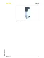
Page 11: ...Fig 2 Mounting of VEGABAR 17 VEGABAR 17 11 4 Mounting 27636 EN 120531 ...

Page 12: ... factors that influence the operating voltage l Output voltage of the power supply unit can be lower under nominal load with a sensor current of 20 5 mA or 22 mA in case of fault message l Influence of additional instruments in the circuit see load values in chapter Technical data The instrument is connected with standard two wire cable without screen If electromagnetic interference is expected whic...

Page 13: ...und terminal in the sensor and the outer ground terminal on the housing not to potential equalisation Information The metallic parts of the instrument antenna transmitter concentric tube etc are conductively connected with the inner and outer ground terminal on the housing This connection exists either as a direct metallic contact or via the shielding of the special connection cable on instruments...

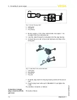
Page 14: ...o the screw terminals according to the wiring plan 2 3 1 4 Fig 4 Connection to the screw terminals 1 Cable gland 2 Plug housing 3 Plug insert 4 Plug seal 7 Snap the plug insert into the plug housing and insert the sensor seal 8 Plug the plug insert with seal to VEGABAR 17 and tighten the screw The electrical connection is finished Proceed as follows Connection via angle plug connector with hin ged ...

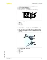
Page 15: ... relief 3 Cable gland 4 Plug housing 5 Remove approx 5 cm of the cable mantle strip approx 1 cm insulation from the individual wires 6 Lead the cable through the cable gland into the plug housing 7 Connect the wire ends to the screw terminals according to the wiring plan 1 5 2 3 4 Fig 6 Connection to the screw terminals 1 Cable gland 2 Cover 3 Plug housing 4 Plug insert 5 Plug seal VEGABAR 17 15 5...

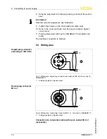
Page 16: ... tighten the screw The electrical connection is finished 5 3 Wiring plan 1 2 3 1 Fig 7 Wiring plan angle plug connector according to ISO 4400 top view to VEGABAR 17 1 Voltage supply and signal output 3 1 3 2 4 1 Fig 8 Wiring plan round plug connector M12 x 1 top view to VEGABAR 17 1 Voltage supply and signal output Connection via connection cable with 4 pole socket M12 x 1 accessory Angled plug con...

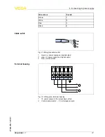
Page 17: ...pply and signal output 2 green power supply and signal output 3 blue cable screen 3 2 1 4 5 1 2 Fig 10 Wiring plan terminal housing 1 To power supply or the processing system 2 Control instrument 4 20 mA measurement Cable outlet Terminal housing VEGABAR 17 17 5 Connecting to power supply 27636 EN 120531 ...

Page 18: ...consideration of an installation position different from the reference installation position A shifting of zero shifts span also respectively Note The potentiometer for span should only be used if you have adequate calibration equipment at least 3 times more precise than the deviation of VEGABAR 17 Recommended recalibration cycle 1 year Proceed as follows 1 Loosen the plug connector and screw the s...

Page 19: ...rument plug 5 Plug seal 6 Housing 3 Set zero in unpressurized status check 4 mA signal in the circuit 4 Set span with exact reference pressure 5 Check zero 2 1 Fig 12 Adjustment of zero and span 1 zero Z 2 span S 6 Assemble the instrument and connect it VEGABAR 17 19 6 Setup 27636 EN 120531 ...

Page 20: ...tment of zero and span 1 zero Z 2 span S 2 Set zero in unpressurized status check 4 mA signal in the circuit 3 Set a span with a sufficiently precise reference pressure 4 Check zero 5 Screw the housing cover back on Instruments with termi nal housing 20 VEGABAR 17 6 Setup 27636 EN 120531 ...

Page 21: ... a week round the clock Since we offer this service world wide the support is only available in the English language The service is free of charge only the standard telephone costs will be charged No 4 20 mA signal l Connection to voltage supply wrong à Check connection according to chapter Connection steps and if necessary correct according to chapter Wiring plan l No voltage supply à Check cables...

Page 22: ...help us carry out the repair quickly and without having to call back for needed information l Print and fill out one form per instrument l Clean the instrument and pack it damage proof l Attach the completed form and if need be also a safety data sheet outside on the packaging l Please ask the agency serving you for the address of your return shipment You can find the respective contact data on our ...

Page 23: ...ectronics to be easily separable WEEE directive 2002 96 EG This instrument is not subject to the WEEE directive 2002 96 EG and the respective national laws Pass the instrument directly on to a specialised recycling company and do not use the municipal collecting points These may be used only for privately used products according to the WEEE directive Correct disposal avoids negative effects on huma...

Page 24: ...PA Cable gland PA 316Ti Plug seal Silicone Connection cable PUR Available cable length max 40 m Weight approx Version with plug connector cable outlet 0 2 kg 0 441 lbs Version with terminal housing 0 35 kg 0 772 lbs Torque max 50 Nm 36 88 lbft Output variable Output signal 4 20 mA Zero and span adjustable via potentiometer 5 Dead time 1 ms Step response time 10 90 Standard version 1 ms 2 Synthetic...

Page 25: ...n the type label always apply Nominal range Overload capacity max pressure Overload capacity min pressure Gauge pressure 0 1 0 bar 10 0 kPa 1 bar 100 kPa 1 bar 100 kPa 0 16 0 bar 16 0 kPa 1 5 bar 150 kPa 1 bar 100 kPa 0 25 0 bar 25 0 kPa 2 bar 200 kPa 1 bar 100 kPa 0 4 0 bar 40 0 kPa 2 bar 200 kPa 1 bar 100 kPa 0 6 0 bar 60 0 kPa 4 bar 400 kPa 1 bar 100 kPa 1 0 bar 100 0 kPa 5 bar 500 kPa 1 bar 10...

Page 26: ...Pa 10 bar 1000 kPa 0 4 bar 0 400 kPa 17 bar 1700 kPa 0 6 bar 0 600 kPa 35 bar 3500 kPa 0 10 bar 0 1000 kPa 35 bar 3500 kPa 0 16 bar 0 1600 kPa 80 bar 8 MPa Deviation4 Deviation 0 5 Influence of the product or ambient temperature5 The following specifications apply to values within the compensated temperature range i e 0 80 C 176 F reference temperature 20 C 68 F Average temperature coefficient of the ...

Page 27: ... 20 80 C 4 176 F 2 1 55 C 131 F 80 C 176 F 130 C 266 F 150 C 302 F Fig 14 Temperature derating VEGABAR 17 1 Ambient temperature 2 Process temperature Storage and transport temperature Standard 30 100 C 22 212 F with cooling element 20 100 C 4 212 F Process conditions Product temperature Standard 30 100 C 22 212 F additional 30 125 C 22 257 F with cooling element 20 150 C 4 302 F Measuring ranges f...

Page 28: ...1 Cable outlet Diameter 6 8 mm Terminal housing Cable entry for cable outer diameter 6 8 mm Spring loaded terminals for wire cross section up to 2 5 mm AWG 14 Voltage supply Operating voltage Version with plug or cable outlet 10 30 V DC Version with terminal housing 11 30 V DC Load Version with cable outlet RA U 10V 0 02 A length of the cable version in m x 0 14 Ω Version with plug see diagram Ver...

Page 29: ...truments with approvals can have different technical data depending on the version That s why the associated approval documents have to be noted with these instruments They are part of the delivery or can be downloaded under www vega com via VEGA Tools and serial number search as well as via Downloads and Approvals VEGABAR 17 29 9 Supplement 27636 EN 120531 ...

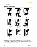
Page 30: ...5 mm 0 81 10 mm 0 39 126 mm 4 96 ø 30 mm 1 18 SW41 G1 28 mm 1 10 135 mm 5 31 ø 30 mm 1 18 1 4NPT 1 2NPT 116 mm 4 57 13 mm 0 51 123 mm 4 84 19 mm 0 75 GBX NBX NDX 84L 84B GDX TBX 851 85L 85B 861 86L 86B GTX Fig 15 VEGABAR 17 standard housing GBX G B manometer connection GDX G B manometer connection GTX G A according to DIN 3852 E TBX G B inside G B 84L 84B G1 B front flush max 25 bar 851 85L 85B G1 ...

Page 31: ...5 10 mm 0 39 139 5 mm 5 49 20 5 mm 0 81 20 5 mm 0 81 20 mm 0 79 3 mm 0 12 ø 17 5 mm 0 69 146 mm 5 75 143 mm 5 63 146 mm 5 75 143 mm 5 63 19 mm 0 75 GBX NBX NDX 84L 84B GDX TBX 851 85L 85B 861 86L 86B GTX Fig 16 VEGABAR 17 standard housing GBX G B manometer connection GDX G B manometer connection GTX G A according to DIN 3852 E TBX G B inside G B 84L 84B G1 B front flush max 25 bar 851 85L 85B G1 B ...

Page 32: ... 0 55 10 mm 0 39 131 5 mm 5 18 20 5 mm 0 81 20 mm 0 79 3 mm 0 12 ø 17 5 mm 0 69 19 mm 0 75 ø 6 1 m m 2 4 0 max 90 mm 3 54 138 mm 5 43 138 mm 5 43 135 mm 5 31 GBX NBX NDX 84L 84B GDX TBX 851 85L 85B 861 86L 86B GTX Fig 17 VEGABAR 17 terminal housing GBX G B manometer connection GDX G B manometer connection GTX G A according to DIN 3852 E TBX G B inside G B 84L 84B G1 B front flush max 25 bar 851 85L...

Page 33: ...5 mm 0 69 27 5 mm 1 08 17 5 mm 0 69 13 5 mm 0 53 12 mm 0 47 1 2 3 4 5 Fig 18 VEGABAR 17 Cooling elements plug cable outlet 1 Cooling element G B 2 Cooling element G1 B 3 Plug according to ISO 4400 4 Cable outlet 5 M12 x 1 plug VEGABAR 17 33 9 Supplement 27636 EN 120531 ...

Page 34: ...34 VEGABAR 17 9 Supplement 27636 EN 120531 ...

Page 35: ...VEGABAR 17 35 9 Supplement 27636 EN 120531 ...

Page 36: ...y application practical use and operating conditions of the sensors and processing systems correspond to the information avail able at the time of printing VEGA Grieshaber KG Schiltach Germany 2012 Subject to change without prior notice 27636 EN 120531 ...

Reviews: