background image

I

f condensate forms on the vessel top

,

the run

-

o

liquid can cause

bridging and hence measurement errors

.

F

or this reason

,

use a screening tube or a longer insulation

.

T

he length

depends on the amount of condensate and the drain

-

o

behaviour of

the product

.

4

.

2

M

ounting instructions

D

uring operation

,

the probe must not touch any installations or the

vessel wall

.

T

he measured value can also change if the distance to the

vessel wall changes considerably

.

I

f necessary

,

secure the end of the

probe

(

insulated

).

1

2

1

2

F

ig

.

4

:

F

asten the probe

1

P

robe

2

P

lastic socket

I

n vessels with conical bottom it can be advantageous to mount the

sensor in the center of the vessel

,

as measurement is then possible

down to the lowest point of the vessel bottom

.

I

f the instrument is mounted in the

lling stream

,

unwanted false

measurement signals can be generated

.

F

or this reason

,

mount the

instrument at a position in the vessel where no disturbances

,

e

.

g

.

from

lling openings

,

agitators

,

etc

.,

can occur

.

T

his applies particularly to instrument versions with a longer probe

.

C

ondensation

M

ounting position

I

n

owing medium

VEGACAL

62

P

ro

bus

PA

13

4

M

ounting

30025

-

EN

-

090603

Summary of Contents for VEGACAL 62

Page 1: ...Operating Instructions VEGACAL 62 Pro bus PA Document ID 30025 Capacitive...

Page 2: ...ons 13 5 Connect to power supply 5 1 Prepare the connection 15 5 2 Connection procedure 16 5 3 Wiring plan single chamber housing 17 5 4 Wiring plan double chamber housing 19 5 5 Wiring plan double ch...

Page 3: ...entation Information Supplementary documents appropriate to the ordered version come with the delivery You can nd them listed in chapter Product description Instructions manuals for accessories and re...

Page 4: ...d put into practice by them 1 3 Symbolism used Information tip note This symbol indicates helpful additional information Caution If this warning is ignored faults or malfunctions can result Warning If...

Page 5: ...Arbitrary conversions or modi cations are explicitly forbidden 2 3 Warning about misuse Inappropriate or incorrect use of the instrument can give rise to application speci c hazards e g vessel over ll...

Page 6: ...meter adjustment of the basic sensor functions is independ ent of the software version The range of available functions depends on the respective software version of the individual components 2 8 Safe...

Page 7: ...i c Safety instructions with Ex versions if necessary further certi cates VEGACAL 62 consists of the following components l Process tting with probe l Housing with electronics l Housing cover optional...

Page 8: ...reas of industrial process measurement Partly insulated probes such as VEGACAL 62 are preferably used in bulk solids However the probe can also be used in non conductive liquids such as e g oil Probe...

Page 9: ...the indicating and adjustment module is powered by the sensor Prerequisite is a certain level of operating voltage The data for power supply are speci ed in chapter Technical data The optional heatin...

Page 10: ...e left closed and stored according to the orientation and storage markings on the outside Unless otherwise indicated the packages must be stored only under the following conditions l Not in the open l...

Page 11: ...re beginning the welding work remove the electronics module from the sensor By doing this you avoid damage to the electronics through inductive coupling With threaded versions the housing must not be...

Page 12: ...h as those made of copper or lead etc Insulating measures such as covering the thread with Te on tape can interrupt the necessary electrical connection with metal vessels For this reason ground the pr...

Page 13: ...e end of the probe insulated 1 2 1 2 Fig 4 Fasten the probe 1 Probe 2 Plastic socket In vessels with conical bottom it can be advantageous to mount the sensor in the center of the vessel as measuremen...

Page 14: ...Fig 5 In owing medium 14 VEGACAL 62 Pro bus PA 4 Mounting 30025 EN 090603...

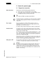
Page 15: ...er the same two wire connection cable Use cable with round cross section A cable outer diameter of 5 9 mm 0 2 0 35 in ensures the seal e ect of the cable gland If you are using cable with a di erent d...

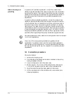
Page 16: ...ents are thus suppressed but the protective e ect against high frequency interference signals remains The total capacitance of the cable and of all capacitors must not exceed 10 nF in Ex applications...

Page 17: ...em 10 Connect the screen to the internal ground terminal connect the outer ground terminal with potential equalisation 11 Tighten the compression nut of the cable entry The seal ring must completely e...

Page 18: ...Aluminium and stainless steel I C Display 1 2 5 6 7 8 3 4 1 2 Fig 8 Electronics and connection compartment single chamber housing 1 Plug connector for VEGACONNECT I C interface 2 Spring loaded termina...

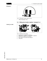
Page 19: ...a versions The Exd version is described in the next subchapter 1 2 3 4 5 Fig 10 Double chamber housing 1 Housing cover connection compartment 2 Blind stopper or plug M12 x 1 for VEGADIS 61 optional 3...

Page 20: ...compartment 3 Terminals for VEGADIS 61 3 1 2 Display 1 2 I C Fig 12 Connection compartment double chamber housing 1 Plug connector for VEGACONNECT I C interface 2 Ground terminal for connection of th...

Page 21: ...2 3 4 5 Fig 14 Double chamber housing 1 Housing cover connection compartment 2 Blind stopper or plug M12 x 1 for VEGADIS 61 optional 3 Housing cover electronics compartment 4 Filter element for air pr...

Page 22: ...ble to the connection compartment 3 Terminals for VEGADIS 61 1 2 1 2 Fig 16 Connection compartment double chamber housing Ex d 1 Spring loaded terminals for power supply and cable screen 2 Ground term...

Page 23: ...utput 5 6 Wiring plan version IP 66 IP 68 1 bar 1 2 Fig 18 Wire assignment connection cable 1 brown and blue to power supply or to the processing system 2 Shielding Wiring plan Wire assignment con nec...

Page 24: ...on on adjustment in the operating instructions manual Indicating and adjustment module 6 2 Insert indicating and adjustment module The indicating and adjustment module can be inserted into the sensor...

Page 25: ...nd to retro t the instrument with an indicating and adjustment module for continuous measured value indication a higher cover with an inspection glass is required VEGACAL 62 Pro bus PA 25 6 Set up wit...

Page 26: ...upt input jump to the next higher menu The sensor is adjusted via the four keys of the indicating and adjustment module The LC display indicates the individual menu items The functions of the individu...

Page 27: ...be emptied or lled completely you can carry out the adjustment also with two known levels for example with 10 and 90 The di erence between the empty and full adjustment values should be as large as p...

Page 28: ...the menu item Basic adjustment with and con rm with OK Now the menu item Min adjustment is displayed Min adjustment 0 00 0 0 pF 54 5 pF 3 Prepare the adjustment value for editing with OK Move to the...

Page 29: ...pacitance value 3 Enter the current capacitance value in pF displayed below for the full vessel corresponding to the percentage value 4 Save the settings with OK To suppress uctuations in the measured...

Page 30: ...r proportional to the level This must be taken into consideration by the user particularly when adjusting the switching point on the level switch In this menu item you can enter an unambiguous designa...

Page 31: ...cale Unit PV Out Scale 0 00 lin 0 0 100 0 lin 100 Information All additional settings are reset to the standard values of the Pro bus PA speci cation Special parameters All special parameters are rese...

Page 32: ...e 1 6 Damping 0 s 1 7 Sensor TAG Sensor Display 2 Basic adjustment Display Diagnostics Service Info 2 1 Displayed value Primary Value 2 4 Lighting Switched o Diagnostics 3 Basic adjustment Display Dia...

Page 33: ...set 4 6 Language Deutsch 4 7 Copy sensor data Copy sensor data 4 8 PIN Enable Info 5 Basic adjustment Display Diagnostics Service Info 5 1 Sensor type VEGACAL 6x Serial number 12345678 5 2 Date of man...

Page 34: ...o indicating and adjustment module The procedure is described in the operating instructions manual Indicating and adjustment module in the menu item Copy sensor data The data remain there permanently...

Page 35: ...C 2 VEGACONNECT 3 Sensor 1 2 3 4 O P E N TWIST USB L O C K Fig 22 Connection via VEGACONNECT externally 1 I C bus com interface on the sensor 2 I C connection cable of VEGACONNECT 3 VEGACONNECT 4 USB...

Page 36: ...n this DTM Collection incl the basic version of PACTware can be downloaded free of charge from the Internet Move via www vega com and Downloads to Software 7 3 Parameter adjustment with AMS and PDM Fo...

Page 37: ...uccessful call the VEGA service hotline in urgent cases under the phone no 49 1805 858550 The hotline is available to you 7 days a week round the clock Since we o er this service world wide the suppor...

Page 38: ...us and terminate if necessary according to the speci cation l Instrument not connected to the segment double assignment of an address Check and correct if necessary In Ex applications the regulations...

Page 39: ...rry out a software update or send the instrument for repair E113 l Communication con ict Exchange instrument or return instrument for repair Depending on the failure reason and measures taken the step...

Page 40: ...nd are suitable for all series 60 sensors The following types are available l CL E60H 4 20 mA HART l CL E60P Pro bus PA l CL E60F Foundation Fieldbus In Ex applications only one electronics module wit...

Page 41: ...outside on the packaging l Please ask the agency serving you for the address of your return shipment You can nd the respective agency on our website www vega com under Company VEGA worldwide VEGACAL 6...

Page 42: ...be easily separable WEEE directive 2002 96 EG This instrument is not subject to the WEEE directive 2002 96 EG and the respective national laws Pass the instrument directly on to a specialised recycli...

Page 43: ...inless steel housing investment casting silicone Aluminium plastic housing stainless steel housing electro polished Ground terminal 316L Process ttings Pipe thread cylindrical ISO 228 T1 G A G A G1 A...

Page 44: ...of the complete measuring range Ambient conditions Ambient storage and transport temperature 40 80 C 40 176 F Process conditions Process pressure 1 64 bar 100 6400 kPa 14 5 928 psig Process temperatur...

Page 45: ...x 1 for VEGADIS 61 or l 1 x plug depending on the version 1 x blind stopper M20 x 1 5 1 x blind stopper M16 x 1 5 or optionally available with 1 x plug M12 x 1 for VEGADIS 61 Spring loaded terminals...

Page 46: ...d indicating and adjustment module Non Ex instrument 12 32 V DC EEx ia instrument 12 24 V DC EEx d instrument 20 32 V DC Power supply by max number of sensors DP PA segment coupler max 32 max 10 with...

Page 47: ...For these instruments the corresponding approval documents have to be taken into account These are part of the delivery or can be downloaded under www vega com via VEGA Tools and serial number search...

Page 48: ...D Optionally to this manufacturer speci c GSD le PNO provides also a general so called pro le speci c GSD le For VEGACAL 62 you have to use the general GSD le PA139700 GSD If the general GSD le is use...

Page 49: ...uration software Note The modules are available in two versions l Short for Pro bus master supporting only one Identi er Format byte e g Allen Bradley l Long for Pro bus master only supporting the Ide...

Page 50: ...2 Bit 5 2 Bit 4 2 Bit 3 2 Bit 2 2 Bit 1 2 Bit 0 2 Sign Bit Significant 7 6 5 4 3 2 1 0 1 2 3 4 5 6 7 Byte n 2 Byte n 3 Bit 7 2 Significant Bit 6 2 Bit 5 2 Bit 4 2 Bit 3 2 Bit 2 2 Bit 1 2 Bit 0 2 Bit 7...

Page 51: ...ailsafe replacement value Failsafe Mode Last valid value and no valid measured value since switching on 0x51 uncertain sensor conversion not accurate low limited Sensor value lower limit 0x52 uncertai...

Page 52: ...7 M20x1 5 M20x1 5 NPT 59 mm 2 32 80 mm 3 15 112 mm 4 41 M20x1 5 NPT 1 5 3 6 2 4 Fig 30 Housing versions in protection IP 66 IP 68 0 2 bar with integrated indicating and adjustment module the housing i...

Page 53: ...bar with integrated indicating and adjustment module the housing is 9 mm 0 35 in higher 1 Aluminium housing 2 Stainless steel housing precision casting 2 Stainless steel double chamber housing precis...

Page 54: ...102 mm 4 02 40 mm 1 58 Fig 33 Temperature adapter 16 mm 0 63 L 7 mm 0 28 Fig 34 VEGACAL 62 screening tube fro example against strong condensation 54 VEGACAL 62 Pro bus PA 10 Supplement 30025 EN 090603...

Page 55: ...0 63 L Fig 35 VEGACAL 62 concentric tube for exmaple with small dielectric gure or for linearization L Concentric tube length see chapter Technical data VEGACAL 62 Pro bus PA 55 10 Supplement 30025 EN...

Page 56: ...s lignes de produits VEGA sont globalement prot g es par des droits de propri t intellectuelle Pour plus d informations on pourra se r f rer au site http www vega com VEGA lineas de productos est n pr...

Page 57: ...VEGACAL 62 Pro bus PA 57 10 Supplement 30025 EN 090603...

Page 58: ...58 VEGACAL 62 Pro bus PA 10 Supplement 30025 EN 090603...

Page 59: ...VEGACAL 62 Pro bus PA 59 10 Supplement 30025 EN 090603...

Page 60: ...vega com Printing date ISO 9001 All statements concerning scope of delivery application practical use and operating conditions of the sensors and processing systems correspond to the information avail...

Reviews: