background image

24

5 Connecting to power supply

VEGACAL 66 • Foundation Fieldbus

30038-EN-200929

I2C

1

1

2

Fig. 15: Wiring plan - double chamber housing
1  Voltage supply, signal output

5.5  Wiring plan, Ex-d double chamber housing

1

2

3

4

5

Fig. 16: Double chamber housing
1  Housing cover - connection compartment

2  Blind plug or plug M12 x 1 for VEGADIS 81 (optional)

3  Housing cover - electronics compartment

4  Filter element for air pressure compensation

5  Cable gland

1

3

2

Display

1 2

5 6 7 8

I2C

Fig. 17: Electronics compartment - double chamber housing
1  Plug connector for VEGACONNECT (I²C interface)

2  Internal connection cable to the connection compartment

3  Terminals for VEGADIS 81

Wiring plan

Housing overview

Electronics compartment

Summary of Contents for VEGACAL 66

Page 1: ...Operating Instructions Capacitive cable electrode for continuous level measurement VEGACAL 66 Foundation Fieldbus Document ID 30038...

Page 2: ...ons 14 4 2 Mounting instructions 16 5 Connecting to power supply 19 5 1 Preparing the connection 19 5 2 Connection procedure 20 5 3 Wiring plan single chamber housing 20 5 4 Wiring plan double chamber...

Page 3: ...2 Rectify faults 44 9 3 Exchanging the electronics module 45 9 4 How to proceed if a repair is necessary 46 10 Dismount 47 10 1 Dismounting steps 47 10 2 Disposal 47 11 Supplement 48 11 1 Technical d...

Page 4: ...t ID By entering the Document ID on www vega com you will reach the document download Information note tip This symbol indicates helpful additional infor mation and tips for successful work Note This...

Page 5: ...lying with all prevailing regulations and directives The instrument must only be operated in a technically flawless and reliable condition The operator is responsi ble for the trouble free operation o...

Page 6: ...Installations in the US shall comply with the relevant requirements of the National Electrical Code ANSI NFPA 70 Installations in Canada shall comply with the relevant requirements of the Canadian El...

Page 7: ...tes Information Optional instrument features are also described in this operating instructions manual The respective scope of delivery results from the order specification This operating instructions...

Page 8: ...2 3 Fig 1 VEGACAL 66 cable version with plastic housing 1 Housing lid with integrated display and adjustment module optional 2 Housing with electronics 3 Process fitting The type label contains the mo...

Page 9: ...via www vega com Search You can find the serial number on the inside of the instrument as well as on the type label on the outside The type label contains the serial number of the instrument With it y...

Page 10: ...to a level proportional signal Power is supplied via the H1 Fieldbus A two wire cable according to Fieldbus specification serves as carrier of both power and digital data for multiple sensors This cab...

Page 11: ...of the packaging material via specialised recycling companies Transport must be carried out in due consideration of the notes on the transport packaging Nonobservance of these instructions can cause...

Page 12: ...ensors with HART protocol It is looped into the 4 20 mA HART signal cable The PLICSMOBILE T81 is an external GSM GPRS UMTS radio unit for transmission of measured values and for remote parameter adjus...

Page 13: ...otective cover protects the sensor housing against soiling and intense heat from solar radiation Screwed flanges are available in different versions according to the following standards DIN 2501 EN 10...

Page 14: ...30 without the use of any tools You can also install the display and adjustment module in four different positions each displaced by 90 Devices with threaded fitting are screwed into the process fitti...

Page 15: ...e g covering the thread with teflon tape can interrupt the necessary electrical connection with metal vessels For this reason ground the probe on the vessel or use a conductive seal material Metal ve...

Page 16: ...ossible to have the cable entries screwed in at the factory The free openings for the cable glands are therefore covered with red dust protection caps as transport protection Prior to setup you have t...

Page 17: ...as measurement is then possible down to the bottom Caution It is not possible to measure on the gravity weight The measuring range of the probe ends at the upper edge of the gravity weight If the inst...

Page 18: ...18 4 Mounting VEGACAL 66 Foundation Fieldbus 30038 EN 200929 Fig 7 Inflowing medium...

Page 19: ...cording to the Fieldbus specification In particular make sure that the bus is termi nated with suitable terminating resistors Metric threads In the case of instrument housings with metric thread the c...

Page 20: ...pprox 1 cm 0 4 in of insulation from the ends of the individual wires 5 Insert the cable into the sensor through the cable entry 6 Lift the opening levers of the terminals with a screwdriver see follo...

Page 21: ...ind plug with version IP66 IP68 1 bar for Aluminium and stainless steel I C 5 1 2 4 3 Display Typ 1 2 5 6 7 8 Bus Sim Fig 10 Electronics and connection compartment single chamber housing 1 Spring load...

Page 22: ...4 Wiring plan double chamber housing The following illustrations apply to the non Ex as well as to the Ex ia version 1 2 3 4 5 Fig 12 Double chamber housing 1 Housing cover connection compartment 2 B...

Page 23: ...or display and adjustment module 3 Interface for service 4 Internal connection cable to the connection compartment 5 Ground terminal for connection of the cable screening 1 2 3 Display 1 2 I2C Fig 14...

Page 24: ...g cover connection compartment 2 Blind plug or plug M12 x 1 for VEGADIS 81 optional 3 Housing cover electronics compartment 4 Filter element for air pressure compensation 5 Cable gland 1 3 2 Display 1...

Page 25: ...ly and cable screen 2 Ground terminal for connection of the cable screening 1 1 2 Fig 19 Wiring plan Ex d ia double chamber housing 1 Voltage supply signal output 5 6 Wiring plan version IP66 IP68 1 b...

Page 26: ...Insert display and adjustment module The display and adjustment module can be inserted into the sensor and removed again at any time It is not necessary to interrupt the voltage supply Proceed as foll...

Page 27: ...list entry Select editing position key Change value of the parameter ESC key Interrupt input Jump to next higher menu The instrument is operated via the four keys of the display and adjustment module...

Page 28: ...l cannot be emptied or filled completely you can carry out the adjustment also with two known levels for example with 10 and 90 The difference between the empty and full adjustment values should be as...

Page 29: ...adjustment is displayed Min adjustment 0 00 0 0 pF 54 5 pF 3 Prepare the adjustment value for editing with OK Move to the selection window with OK Min adjustment Accept current measured value Accept E...

Page 30: ...be longer and the sensor will react to measured value changes with a delay In general a period of a few seconds is sufficient to smooth the measured value display Damping 0 s Enter the requested param...

Page 31: ...o maintain the function of the device the lighting is temporarily switched off if the power supply is insufficient Backlight In the default setting the lightning is switched off The respective min and...

Page 32: ...tput This allows you to test the signal path e g through connected indicating instruments or the input card of the control system The following simulation variables are available Percent Current Press...

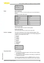
Page 33: ...icator The min and max values are reset to the actual value The sensor is already set to the ordered national language In this menu item you can change the language The following languages are availab...

Page 34: ...ted Measuring principle Signal output Copy sensor data Copy sensor data In this menu item the PIN is activated deactivated permanently Entering a 4 digit PIN protects the sensor data against unauthori...

Page 35: ...ce ID Sensor TAG Device ID max 32 characters Sensor TAG PD_TAG max 32 characters Sensor details e g approval process fitting seal measuring cell measuring range electronics housing cable entry plug ca...

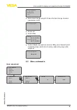
Page 36: ...hed on Diagnostics Basic adjustment 3 Display Diagnostics Service Info Peak value indicator 3 1 Capacit min 65 7 pF Capacit max 782 4 pF Sensor status 3 2 OK Trend recording 3 3 Presentation of the tr...

Page 37: ...5 4 05 March 2012 Sensor characteristics 5 5 Display now 6 6 Saving the parameterisation data We recommended writing down the adjustment data e g in this op erating instructions manual and archiving t...

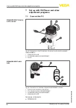
Page 38: ...ensor via the interface adapter VEGACONNECT 1 USB cable to the PC 2 Schnittstellenadapter VEGACONNECT 3 Sensor 1 2 3 4 OP EN TWIST USB LO CK Fig 24 Connection via interface adapter VEGACONNECT externa...

Page 39: ...t all described functions are included in older firmware versions You can download the latest instrument software from our homepage A description of the update procedure is also available in the Inter...

Page 40: ...able on CD from the agency serving you 7 3 Parameter adjustment with AMS and PDM For VEGA sensors instrument descriptions for the adjustment programs AMS and PDM are available as DD or EDD The instru...

Page 41: ...Off Fig 26 Activate Bluetooth 1 Bluetooth switch On Bluetooth active Off Bluetooth not active The security concept of Bluetooth operation absolutely requires that the default setting of the sensor PIN...

Page 42: ...n For access authentication with Bluetooth the modi fied PIN is still effective Information Bluetooth communication functions only if the actual sensor PIN dif fers from the default setting 0000 8 2 C...

Page 43: ...isplayed For the first connection the operating device and the sensor must authenticate each other After successful authentication the next con nection functions without authentication For authenticat...

Page 44: ...ocedure is described below Further comprehensive diagnostics can be carried out on a PC with the software PACTware and the suitable DTM In many cases the causes can be determined and the faults rectif...

Page 45: ...ing of intrinsically safe circuits must be observed Error Cause Rectification E013 no measured value avail able Probe insulation damaged short circuit due to per meating conductive medium Exchange the...

Page 46: ...find a suit able electronics module in the following overview The oscillators differ only in their signal output and are suitable for all series 60 sensors The following types are available CL E60 H 4...

Page 47: ...y spe cialised recycling companies We use recyclable materials and have designed the electronics to be easily separable WEEE directive The instrument does not fall in the scope of the EU WEEE directiv...

Page 48: ...d PTFE Gravity weight 316L Screening tube 316L Materials non wetted parts Probe cable fully PTFE insulated 8 mm 0 315 in 316L Plastic housing Plastic PBT Polyester Aluminium die cast housing Aluminium...

Page 49: ...hannel 1 Primary value Channel 2 Secondary value 1 Channel 3 Secondary value 2 Transmission rate 31 25 Kbit s Current value 10 mA 0 5 mA Damping 63 of the input variable 0 999 s adjustable Input varia...

Page 50: ...mperature 1 Process temperature 2 Ambient temperature Dielectric constant 1 5 Electromechanical data version IP66 IP67 and IP66 IP68 0 2 bar Options of the cable entry Cable entry M20 x 1 5 NPT Cable...

Page 51: ...n window Polyester foil Voltage supply Operating voltage 9 32 V DC Operating voltage UB with lighting switched on 12 32 V DC Power supply by max number of sensors 32 Potential connections and electric...

Page 52: ...Protection class II IEC 61010 1 Approvals Instruments with approvals can have different technical specifications depending on the version For that reason the associated approval documents of these in...

Page 53: ...ALE DIRECT INDIRECT INDIRECT SQRT pF Lin Primary Value Secondary Value 2 Secondary Value 1 AI 2 AI 1 TB Sensor_Value min max adjustment Linearization Channel 1 Primary Value Channel 2 Secondary Value...

Page 54: ...NNEL 1 is selected The unit is defined in primary_value_unit primary_value_unit Selected unit code for primary_value secondary_value_1 This is the process value after adjustment with the status of the...

Page 55: ...d point of the sensor_value It refers to cal_ level_hi The unit is defined in sensor_range Units Index Calibration Lowest Point Min Max adjustment this is the lower calibrated point of the sensor_valu...

Page 56: ...9 mm 2 72 79 mm 3 11 112 mm 4 41 M20x1 5 NPT 84 mm 3 31 M16x1 5 112 mm 4 41 M20x1 5 NPT 1 2 79 mm 3 11 Fig 31 Housing versions in protection IP66 IP67 with integrated display and adjustment module the...

Page 57: ...2 L G 1 G 1 56 mm 2 21 12 mm 0 47 20 mm 0 79 36 mm 1 42 30 mm 1 18 22 mm 0 87 1 2 Fig 33 VEGACAL 66 threaded version G1 ISO 228 T1 L Sensor length see chapter Technical data 1 Gravity weight Process f...

Page 58: ...nt VEGACAL 66 Foundation Fieldbus 30038 EN 200929 16 mm 0 63 27 mm 1 06 L 7 mm 0 28 Fig 34 VEGACAL 66 screening tube for example against strong condensation L Length of the screening tube see chapter...

Page 59: ...nen unter www vega com Les lignes de produits VEGA sont globalement prot g es par des droits de propri t intellec tuelle Pour plus d informations on pourra se r f rer au site www vega com VEGA lineas...

Page 60: ...of delivery application practical use and operat ing conditions of the sensors and processing systems correspond to the information available at the time of printing Subject to change without prior n...

Reviews: