31
6 Set up with the display and adjustment module PLICSCOM
VEGACAL 66 • Foundation Fieldbus
30038-EN-200929
Menu section, display
Radar, guided microwave and ultrasonic sensors deliver the following
measured values:
•
SV1 (Secondary Value 1): Percentage value after the adjustment
•
SV2 (Secondary Value 2): Distance value before the adjustment
•
PV (Primary Value): Linearised percentage value
•
AI FB1 (Out)
In the menu item "
Display
" you can define which value should be
indicated on the display.
Displayed value
AI-Out
A background lighting integrated by default can be adjusted via the
adjustment menu. The function depends on the height of the supply
voltage. See "
Technical data/Voltage supply
".
To maintain the function of the device, the lighting is temporarily
switched off if the power supply is insufficient.
Backlight
In the default setting, the lightning is switched off.
The respective min. and max. measured values are saved in the sen-
sor. The values are displayed in the menu item "
Peak values
".
•
Min. and max. distance in m(d)
•
Min. and max. temperature
Peak value indicator
The instrument status is displayed in this menu item. If no failure is
detected by the sensor, "
OK
" will be displayed. If a failure is detected,
there will be a sensor-specific flashing fault signal, for example "
E013
". The failure is also displayed in clear text, for example "
No
measured value available
".
Information:
The fault message as well as the clear text indication are also carried
out in the measured value display.
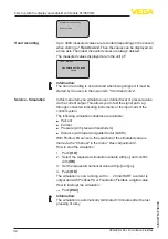
Display - Indicated value
Display - Backlight
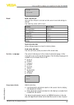
Diagnosis - Peak value
Diagnostics - Device
status


