12
VEGADIS 371 Ex
• Set the rotating switch (7) to position 2 (relay 1 off).
With the keys (3 and 4) you can change the value of
the indication. For the given example you set the
digital indication (8) to the value 10,0 (10,0 %).
Hence the internal relay 1 switches off when this
value is decreased. The appropriate relay control
lamp (2) lights when the relay is energized. When
the switch points are too close together (< 0,1 %),
the appropriate LED flashes. The relay takes the
safe condition. In mode "Operate“ a fault signal is
displayed.
• When you want to control further relays, proceed in
the same way than for relay 1.
The positions for adjustment of the appropriate
relays are stated in the list of the rotating switch (7)
under 4.1 Indicating and adjustment elements.
Note
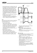
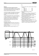
When you want to change the mode (i.e. the switching
function of the relays) you have to exchange the on
and off-values (see fig. 4.2)
• Mode A (overfill protection)
switch on point < switch off point
To adjust e.g. for relay 1 mode A (overfill protection)
you have to enter with position 1 (relay 1 on) of the
rotating switch (7) the lower value and with position
2 (relay 1 off) the higher value. Hence relay 1 is
switched off when the max. level is reached
(deenergized condition) and switched on when min.
level is reached.
• Mode B (dry run protection)
switch on point > switch off point
When you want to adjust mode B (dry run
protection) for relay 1, you have to enter with
position 1 (relay 1 on) of the rotating switch (7) the
higher value and with position 2 (relay 1 off) the
lower value. Hence relay 1 is switched on when
Set-up
max. level is reached and switch off (deenergized
condition) when min. level is reached.
Integration time
• When you want to adjust an integration time
(reaction delay), set the rotating switch (7) to
position 9.
• With the keys (3 and 4) you can change the value of
the indication (0 up to 250 seconds).
Offset correction
As a factory setting, pressure transmitters are adjusted
in a certain position. When the transmitter is
mounted in another position, the measuring range is
shifted.
• Ensure that the sensor is unpressurized.
• To carry out an offset correction, set the rotating
switch (7) to position E (Offset correction). The
display now indicates the actual sensor current in
mA or the voltage in V.
• Push the plus and minus key (3 and 4) together.
The measuring range is not modified, but
completely shifted.
• Set the rotating switch (7) to position 0 (OPERATE).
All adjusted values are transferred to an EEPROM-
memory and saved. They remain there even in case
of a probable voltage loss.
Level
off (on)
on (off)
LED
Relay on
Relay on
Relay off
Mode A
Mode B
t
Mode A (B)
Relay off
Fig. 4.2


