W
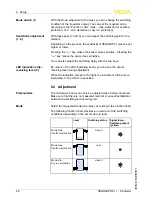
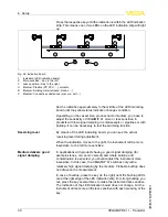
ith the mode adjustment
(
min
./
max
.)
you can change the switching
condition of the transistor output
.
Y
ou can set the required mode
according to the
"
F
unction chart
"
(
max
. -
max
.
detection or over
fl
ow
protection
,
min
. -
min
.
detection or dry run protection
).
W
ith these keys
(
7
and
8
)
you can adjust the switching point to the
medium
.
D
epending on the process
,
the sensitivity of
VEGAMIP
61
must be set
higher or lower
.
P
ressing the
"<
--
"
key makes the sensor more sensitive
.
P
ressing the
"
--
>"
key makes the sensor less sensitive
.
Y
ou can also adjust the switching delay with the two keys
.
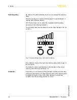
B
y means of the
LED
indicating board
,
you can see the actual
receiving level during adjustment
.
W
hen the indication moves to the right
,
the instrument will be more
insensitive
,
to the left more sensitive
.
6
.
2
A
djustment
T
he microwave barrier can only be adjusted when being uncovered
.
M
ake sure that there is no measured medium or vessel installations
between the emitting and receiving unit
.
S
elect the requested mode
(
min
./
max
.)
according to the function chart
.
T
he following function chart provides an overview of the switching
conditions depending on the set mode and level
.
L
evel
S
witching status
S
ignal lamp
-
S
witching output
(
yellow
)
M
ode max
.
O
ver
fl
ow protection
closed
M
ode max
.
O
ver
fl
ow protection
open
M
ode min
.
D
ry run protection
closed
M
ode switch
(
1
)
S
ensitivity adjustment
(
7
,
8
)
LED
indication strip
-
receiving level
(
9
)
P
rerequisites
M
ode
28
VEGAMIP R
61
• -
T
ransistor
6
S
etup
40694
-
EN
-
120228


