background image

VEGA G

rieshaber

KG

A

m

H

ohenstein

113

77761

S

chiltach

G

ermany

P

hone

+

49 7836 50

-

0

F

ax

+

49 7836 50

-

201

E

-

mail

:

info

.

de

@

vega

.

com

www

.

vega

.

com

P

rinting date

:

ISO 9001

A

ll statements concerning scope of delivery

,

application

,

practical use and operating conditions of the sensors and

processing systems correspond to the information avail

-

able at the time of printing

.

©

VEGA G

rieshaber

KG

,

S

chiltach

/

G

ermany

2012

S

ubject to change without prior notice

40694

-

EN

-

120228

Summary of Contents for VEGAMIP 61

Page 1: ...Operating Instructions VEGAMIP R61 Receiving unit Transistor Document ID 40694 Radar ...

Page 2: ... storage 10 3 4 Accessories and replacement parts 11 4 Mounting 4 1 General instructions 13 4 2 Instructions for installation 13 5 Connecting to power supply 5 1 Preparing the connection 23 5 2 Connection procedure 23 5 3 Wiring plan single chamber housing 25 6 Setup 6 1 Adjustment elements 27 6 2 Adjustment 28 7 Maintenance and fault rectification 7 1 Maintaining 33 7 2 Remove interferences 33 7 3...

Page 3: ...cific safety information for installation and operation in Ex areas These safety instructions are part of the operating instructions manual and come with the Ex approved instruments Editing status 2012 02 14 VEGAMIP R61 Transistor 3 Contents 40694 EN 120228 ...

Page 4: ... put into practice by them 1 3 Symbolism used Information tip note This symbol indicates helpful additional information Caution If this warning is ignored faults or malfunctions can result Warning If this warning is ignored injury to persons and or serious damage to the instrument can result Danger If this warning is ignored serious injury to persons and or destruction of the instrument can result...

Page 5: ...instructions This is a state of the art instrument complying with all prevailing regulations and guidelines The instrument must only be operated in a technically flawless and reliable condition The operator is responsible for the trouble free operation of the instrument During the entire duration of use the user is obliged to determine the compliance of the necessary occupational safety measures wi...

Page 6: ...find the conformity certificate in the download section under www vega com 2 6 Radio license for Europe The instrument is approved according to EN 300440 1 V1 5 1 2009 03 and EN 300440 2 V1 531 2009 03 and can be used without radio limitations 2 7 Radio license for USA Canada Operation is only permitted if the following two conditions are fulfilled l The instrument must not emit interference radiatio...

Page 7: ...ith the goal of continuously improving company environmental protection The environment management system is certified according to DIN EN ISO 14001 Please help us fulfil this obligation by observing the environmental instructions in this manual l Chapter Packaging transport and storage l Chapter Disposal VEGAMIP R61 Transistor 7 2 For your safety 40694 EN 120228 ...

Page 8: ...r search The scope of delivery typically includes the following parts l Point level sensor VEGAMIP R61 receiving unit l Documentation this operating instructions manual Supplementary instructions manual Plug connector for level sensors optional Ex specific Safety instructions with Ex versions if necessary further certificates l The corresponding emitting unit VEGAMIP T61 is described in a separate o...

Page 9: ...high temperatures strong dust generation and abrasive products are all no problem for the instrument The VEGAMIP 61 consists of the following components 3 3 5 4 5 2 1 Fig 1 VEGAMIP 61 with plastic housing 1 Emitting unit VEGAMIP T61 2 Receiving unit VEGAMIP R61 with control electronics 3 Housing cover 4 Housing with control electronics 5 Process fitting VEGAMIP R61 Transistor 9 3 Product descriptio...

Page 10: ...our instrument was protected by packaging during transport Its capacity to handle normal loads during transport is assured by a test according to DIN EN 24180 The packaging of standard instruments consists of environment friendly recyclable cardboard For special versions PE foam or PE foil is also used Dispose of the packaging material via specialised recycling companies Transport must be carried ...

Page 11: ...nse heat from solar radiation You will find additional information in the supplementary instructions manual Protective cover Document ID 34296 Flanges are available in different versions according to the following standards DIN 2501 EN 1092 1 ANSI B 16 5 JIS B 2210 1984 GOST 12821 80 You can find additional information in the supplementary instructions manual Flanges according to DIN EN ASME JIS Docu...

Page 12: ...r for the emitting and the receiving unit The mounting adapter can only be used with the threaded version internal horn antenna with PTFE cover Fig 3 VEGAMIP 61 with high temperature mounting adapter Mounting adapter 12 VEGAMIP R61 Transistor 3 Product description 40694 EN 120228 ...

Page 13: ...see chapter Connecting to power supply and tighten the cable gland You can give your instrument additional protection against moisture penetration by leading the connection cable downward in front of the cable entry Rain and condensation water can thus drain off This applies mainly to outdoor mounting as well as installation in areas where high humidity is expected e g through cleaning processes or...

Page 14: ... 100 mm Cereals corn rice 100 mm Wood chips dry 500 mm Wood chips moist 100 mm Mineral products Ore Stones e g limestone 100 mm Cement clinker 100 mm Glass crushed 100 mm Coal 50 mm Bauxite 100 mm Ore 100 mm If VEGAMIP 61 is mounted in the filling stream unwanted false measurement signals can be generated For this reason mount VEGAMIP 61 at a position in the vessel where no disturbances e g from fil...

Page 15: ...aterial Max thickness of the window material Type of material Window material Max thick ness Plastics PTFE PS 5000 mm PP PE HDPE POM 1000 mm PA PVC PVDF 500 mm Rubber 50 mm Glass or ceramic Inspection glass 200 mm Aluminiumoxide ceramic Al2O3 200 mm Abrasion protection ceramic 100 mm Insulation material Mineral wool 1000 mm Ceramic fibre plates 1000 mm Fireclay bricks 500 mm Metal vessels VEGAMIP R...

Page 16: ...the same as for metal vessels applies to wood vessels due to the liquid absorption of the wood VEGAMIP 61 can be used for detection of products in pipelines In pipelines of non metallic products such as plastic or glass the measured product can be detected through the pipe wall x Fig 7 Installation in pipelines x Min distance 100 mm 3 94 in Mount the threaded version of VEGAMIP 61 in the following...

Page 17: ...olarisation marking 4 4 Hold the instrument in this position and tighten with the counter nut 2 Caution The housing must not be used to screw the instrument in Applying tightening force can damage internal parts of the housing Note In the case of VEGAMIP 61 with NPT thread the instrument seals in the thread itself Hence no counter nut is necessary for these versions Avoid long sockets in which the...

Page 18: ...c or ceramic cylinder to avoid build up of bulk solids and dust deposits Select the material according to the diameter of the socket and adapt the length as far as possible to the shape of the vessel wall Secure the filling material against falling out or turning If using a fixing screw is technically not possible you can secure the material in the socket with an adhesive 18 VEGAMIP R61 Transistor 4...

Page 19: ... should be installed with a mounting adapter or in front of a suitable window In this case you have to use a window material which is appropriately resistant In case of strong vessel vibrations the VEGAMIP 61 should be mounted with anti vibration blocks or rubber buffers Abrasive medium Vibrations VEGAMIP R61 Transistor 19 4 Mounting 40694 EN 120228 ...

Page 20: ... be in a range of 5 Offset The two sensors can have an offset of up to 5 of the sensor distance d to each other Example with a sensor distance of 1000 mm the two sensors must have an offset of max 50 mm to each other General rule the bigger the antenna and the better it focusses the more precise the orientation has to be 5 d d 20 Fig 12 Orientation of the sensors Angle and offset Orientation of the se...

Page 21: ...er 2 1 1 2 Fig 13 Orientation according to the polarisation direction 1 Polarisation marking on top 2 Polarisation marking lateral In tight mounting spaces or spaces subject to high temperatures the signal of VEGAMIP 61 can be guided via a deflector For this you can use a metal plate or an angled antenna extension on the side of the emitting unit In products with low dielectric value we recommend u...

Page 22: ...45 1 2 Fig 14 Possibilities for signal deflection 1 Metal plate for signal deflection of the microwave signal 2 Bent antenna extension 22 VEGAMIP R61 Transistor 4 Mounting 40694 EN 120228 ...

Page 23: ...h standard two wire cable without screen If electromagnetic interference is expected which is above the test values of EN 61326 for industrial areas screened cable should be used Use cable with round cross section A cable outer diameter of 5 9 mm 0 2 0 35 in ensures the seal effect of the cable gland If you are using cable with a different diameter or cross section exchange the seal or use a suitabl...

Page 24: ...gain 6 Check the hold of the wires in the terminals by lightly pulling on them 7 Connect the screen to the internal ground terminal connect the outer ground terminal to potential equalisation 8 Tighten the compression nut of the cable entry The seal ring must completely encircle the cable 9 Screw the housing cover back on The electrical connection is finished Information The terminal block is plugg...

Page 25: ...s 2 and 8 are internally connected Hence PNP or NPN action can be selected through the electrical connection 1 2 Fig 16 Wiring plan receiving unit VEGAMIP 61 receiver PNP action 1 Voltage supply 2 Load 1 2 Fig 17 Wiring plan receiving unit VEGAMIP 61 receiver NPN action 1 Voltage supply 2 Load Wiring plan Connection PNP action Connection NPN action VEGAMIP R61 Transistor 25 5 Connecting to power s...

Page 26: ...1 UH Fig 18 Wiring plan receiving unit VEGAMIP 61 receiver floating 1 Voltage supply UH Auxiliary voltage Connection floating 26 VEGAMIP R61 Transistor 5 Connecting to power supply 40694 EN 120228 ...

Page 27: ...itivity and the switching delay 8 Key for adjustment of the sensitivity and the switching delay 9 LED indicating board for indication of reception strength yellow There are three control lamps LED on the electronics module Control lamp red for indication of a fault 2 This signal lamp shows the fault status of the instrument Control lamp yellow for indication of the switching condition 3 The signal...

Page 28: ...ceiving level during adjustment When the indication moves to the right the instrument will be more insensitive to the left more sensitive 6 2 Adjustment The microwave barrier can only be adjusted when being uncovered Make sure that there is no measured medium or vessel installations between the emitting and receiving unit Select the requested mode min max according to the function chart The follow...

Page 29: ...llow signal lamp lights With the two keys you can change the LED indication strip and adjust the switching point to the medium The keys are lowered to avoid unintentional changes of the setting For adjustment use for example a small screwdriver If you press one of the keys for more than two seconds the adjustment range shifts automatically in the respective direction The greater the distance betwe...

Page 30: ...By means of the LED indicating board you can see the actual receiving level during adjustment When the indication moves to the right the instrument will be more insensitive to the left more sensitive In applications with products having a good signal damping for example stones ore sand cement and where buildup and contamination is expected you should adjust the instrument more insensitive In this ...

Page 31: ...p can be created artifically or imitated In applications with products having a low signal damping for example plastic granules cereals you should adjust the instrument more sensitive Hence the VEGAMIP 61 switches very sensitive even with relatively low covering by the product Fig 30 LED indication strip Setting for products with low signal damping Product delivers low signal damping VEGAMIP R61 Tr...

Page 32: ...Fig 31 Adjust switching delay LED indication flashes If the indication moves to the right the switching delay will be longer to the left shorter The indication returns automatically to the indication of the actual receiving level after approximately 10 s If possible you can simulate a filling between emitting and receiving unit by using the hand or a metal sheet and check if the switching point is a...

Page 33: ... installation location Mount the sensor emitter receiver in a position where there is a lot of measured product between emitting and receiving unit Mount the sensor emitter receiver in a psoition where there are no interfering installations or moving parts Electronics defective Push the mode switch If the instrument then does not change the mode the electronics module may be defective Exchange the...

Page 34: ...module is defective it can be replaced by the user In Ex applications only an electronics module with respective Ex approval may be used You find all information to the electronics exchange in the operating instructions of the new electronics module 7 4 How to proceed in case of repair If a repair is necessary please proceed as follows You can download a return form 23 KB from our homepage at www v...

Page 35: ...ics to be easily separable Correct disposal avoids negative effects on humans and the environ ment and ensures recycling of useful raw materials Materials see chapter Technical data If you have no way to dispose of the old instrument properly please contact us concerning return and disposal WEEE directive 2002 96 EG This instrument is not subject to the WEEE directive 2002 96 EG and the respective ...

Page 36: ...aterials non wetted parts Plastic housing plastic PBT Polyester Aluminium die casting housing Aluminium die casting AlSi10Mg powder coated basis Polyester Stainless steel housing precision cast ing 316L Stainless steel housing electropolished 316L Seal between housing and housing cover NBR stainless steel housing precision casting silicone aluminium plastic housing stainless steel housng electropo...

Page 37: ... adjustable min max Measuring accuracy Hysteresis approximately 1 dB Switching delay adjustable from 0 1 20 s on off Min distance 100 mm 3 94 in Ambient conditions Ambient storage and transport temperature 40 80 C 40 176 F Process conditions Measured variable Limit level of bulk solids and liquids Process pressure3 VEGAMIP 61 threaded version internal horn antenna with PTFE cover 1 4 bar 100 400 kP...

Page 38: ...P 61 with mounting adapter 150 mm optional 40 250 C 40 482 F VEGAMIP 61 with mounting adapter 300 mm optional 40 450 C 40 842 F Electromechanical data Cable entry plug dependent on the version Single chamber housing l 1 x cable entry M20 x 1 5 cable ø 5 9 mm 1 x blind stopper M20 x 1 5 attached 1 x cable entry M20 x 1 5 or l 1 x cable entry NPT 1 x blind stopper NPT 1 x cable entry NPT or l 1 x pl...

Page 39: ...s have to be noted with these instruments They are part of the delivery or can be downloaded under www vega com via VEGA Tools and serial number search as well as via Downloads and Approvals VEGAMIP R61 Transistor 39 9 Supplement 40694 EN 120228 ...

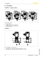
Page 40: ...T 1 3 4 2 Fig 32 Housing versions 1 Plastic housing 2 Stainless steel housing electropolished 3 Stainless steel housing precision casting 4 Aluminium housing VEGAMIP 61 22 mm 0 87 83 mm 3 27 SW 46 mm 1 42 SW 46 mm 1 42 SW 60 mm 1 42 G1 A 1 NPT 83 mm 3 27 1 2 Fig 33 VEGAMIP 61 threaded version 1 Threaded version internal horn antenna with PTFE cover G1 A 2 Threaded version internal horn antenna wit...

Page 41: ...75 mm 2 95 ø 115 mm 4 53 99 5 mm 3 92 ø 44 mm 1 73 Fig 34 VEGAMIP 61 encapsulated antennas 1 Encapsulated horn antenna with PTFE cover flange version 2 Plastic encapsulated antenna with PP cover 3 Mounting strap 4 Adapter flange VEGAMIP R61 Transistor 41 9 Supplement 40694 EN 120228 ...

Page 42: ...3 4 x y 1 2 3 4 x y G1 A 1 NPT 1 Fig 35 VEGAMIP 61 horn antenna 316L VEGAMIP 61 Mounting adapter 40 450 C 24 mm 0 95 x 61 mm 2 4 G2 A Fig 36 Mounting adapter with ceramic cover for VEGAMIP 61 threaded version G2 A with PTFE cover also with 2 NPT thread x 150 mm 5 9 in or 300 mm 11 8 in 42 VEGAMIP R61 Transistor 9 Supplement 40694 EN 120228 ...

Page 43: ...intellectuelle Pour plus d informations on pourra se référer au site http www vega com VEGA lineas de productos están protegidas por los derechos en el campo de la propiedad industrial Para mayor información revise la pagina web http www vega com Линии продукции фирмы ВЕГА защищаются по всему миру правами на интеллектуальную собственность Дальнейшую информацию смотрите на сайте http www vega com V...

Page 44: ...ounting adapter 12 42 O Operation 27 Orientation of the sensor 20 P Packaging 10 Pipelines 16 Polarisation direction 20 Potential equalisation 23 R Receiving unit 9 25 27 Repair 34 S Scope of delivery 8 Sensitivity adjustment 29 Service hotline 34 Shielding 23 Simulation 32 Storage 11 Switching delay 32 Switching point 13 T Threaded version 16 40 Type label 8 Type of vessel Concrete vessel 16 Meta...

Page 45: ...VEGAMIP R61 Transistor 45 Index 40694 EN 120228 ...

Page 46: ...46 VEGAMIP R61 Transistor Index 40694 EN 120228 ...

Page 47: ...VEGAMIP R61 Transistor 47 Index 40694 EN 120228 ...

Page 48: ... vega com Printing date ISO 9001 All statements concerning scope of delivery application practical use and operating conditions of the sensors and processing systems correspond to the information avail able at the time of printing VEGA Grieshaber KG Schiltach Germany 2012 Subject to change without prior notice 40694 EN 120228 ...

Reviews: