background image

77

Notes

VEGAPULS 65 • Foundation Fieldbus

36518-EN-140209

Summary of Contents for VEGAPULS 65

Page 1: ...Operating Instructions Radar sensor for continuous level measurement of liquids VEGAPULS 65 Foundation Fieldbus Document ID 36518...

Page 2: ...3 4 2 Mounting instructions 13 5 Connecting to the bus system 5 1 Preparing the connection 19 5 2 Connecting 20 5 3 Wiring plan single chamber housing 22 5 4 Wiring plan double chamber housing 22 5 5...

Page 3: ...r is needed 53 10 Dismounting 10 1 Dismounting steps 54 10 2 Disposal 54 11 Supplement 11 1 Technical data 55 11 2 Supplementary information Foundation Fieldbus 60 11 3 Dimensions 71 Safety instructio...

Page 4: ...rsonnel and put into practice by them 1 3 Symbolism used Information tip note This symbol indicates helpful additional information Caution If this warning is ignored faults or malfunctions can result...

Page 5: ...instrument complying with all prevailing regulations and guidelines The instrument must only be operated in a technically flawless and reliable condition The operator is responsible for the trouble f...

Page 6: ...s the standard in field instrumentation The device fulfills the requirements of the following NAMUR recom mendations NE 21 Electromagnetic compatibility of equipment NE 43 Signal level for malfunction...

Page 7: ...at is why we have introduced an environment management system with the goal of continuously improving company environmental pro tection The environment management system is certified according to DIN...

Page 8: ...2 Data Matrix Code for Smartphone App 13 Symbol of the device protection class 14 ID numbers instrument documentation 15 Reminder to observe the instrument documentation 16 Notified authority for CE m...

Page 9: ...pplementary instructions GSM GPRS radio module optional Supplementary instructions manual Heating for display and adjustment module optional Supplementary instructions manual Plug connector for con ti...

Page 10: ...ed defects must be appropriately dealt with Up to the time of installation the packages must be left closed and stored according to the orientation and storage markings on the outside Unless otherwise...

Page 11: ...is sion of measured values and for remote parameter adjustment of plics sensors The adjustment is carried out via PACTware DTM by using the integrated USB connection You can find further information i...

Page 12: ...ULS 65 Foundation Fieldbus 36518 EN 140209 VEGAPULS series 60 VEGAFLEX 80 series VEGABAR series 80 You can find further information in the operating instructions Supple mentary electronics for Foundat...

Page 13: ...rough cleaning processes Installations on cooled or heated vessels Make sure that all parts of the instrument exposed to the process are suitable for the existing process conditions These are mainly A...

Page 14: ...rings to compensate the preload loss of the PTFE washer 2 1 Fig 2 Use of disc springs 1 Single disc spring 2 Laminated disc spring 3 Tighten screws with the necessary torque see chapter Technical data...

Page 15: ...ment see chapter Setup If you cannot maintain this distance you should carry out a false signal storage during setup This applies particularly if buildup on the vessel wall is expected In such a case...

Page 16: ...stream Make sure that you detect the product surface not the inflowing product Fig 6 Mounting of the radar sensor with inflowing medium The active part of the antenna i e the conical antenna part sho...

Page 17: ...ce where no other equipment or fixtures cross the path of the microwave signals Vessel installations such as e g ladders limit switches heating spi rals struts etc can cause false echoes and impair th...

Page 18: ...e saved with the blades in different positions Fig 10 Agitators Through the action of filling stirring and other processes in the vessel dense foams which considerably damp the emitted signals may for...

Page 19: ...nical data Make sure that the cable screening and ground is executed accord ing to the Fielbus specification If electromagnetic interference is expected which is above the test values of EN 61326 1 fo...

Page 20: ...this lift the terminal block with a small screwdriver and pull it out When reinserting the terminal block you should hear it snap in Proceed as follows 1 Unscrew the housing cover 2 If a display and...

Page 21: ...the terminal opening is then free When the screwdriver is released the terminal closes again You can find further information on the max wire cross section under Technical data Electromechanical data...

Page 22: ...erface adapter 3 Simulation switch 1 mode for simulation release 4 For external display and adjustment unit 5 Ground terminal for connection of the cable screen 5 4 Wiring plan double chamber housing...

Page 23: ...nd terminal for connection of the cable screen Information The use of an external display and adjustment unit and a display and adjustment module in parallel in the connection compartment is not suppo...

Page 24: ...n switch 1 mode for simulation release 4 Internal connection to the plug connector for external display and adjust ment unit optional Bus 2 1 2 1 Fig 18 Connection compartment double chamber housing E...

Page 25: ...chamber housing with DIS ADAPT 3 1 2 Fig 20 View to the electronics compartment 1 DIS ADAPT 2 Internal plug connection 3 Plug connector M12 x 1 3 4 1 2 Fig 21 Top view of the plug connector 1 Pin 1 2...

Page 26: ...a self test for approx 30 seconds The following steps are carried out Internal check of the electronics Indication of the instrument type hardware and software version measurement loop name on the di...

Page 27: ...by 90 It is not necessary to interrupt the power supply Proceed as follows 1 Unscrew the housing cover 2 Place the display and adjustment module in the requested posi tion onto the electronics and tu...

Page 28: ...ronics compartment 2 In the connection compartment with Ex d ia version not possible Note If you intend to retrofit the instrument with a display and adjustment module for continuous measured value in...

Page 29: ...plication conditions via the pa rameter adjustment The parameter adjustment is carried out with an adjustment menu The main menu is divided into five sections with the following func tions Setup Setti...

Page 30: ...properties is considerably increased Enter the requested parameters via the appropriate keys save your settings with OK and jump to the next menu item with the ESC and the key In addition to the medi...

Page 31: ...e echoes Stable and reliable measured values by averaging High accuracy because not adjusted for max speed False signal suppression recommended Storage tank on ships Cargo Tank Product speed slow fill...

Page 32: ...ts Shifting of the running time in the tube Process measurement conditions Condensation Buildup Properties sensor Measurement speed optimized through little averaging Entering the tube inside diameter...

Page 33: ...signal suppression required Open water gauge measurement Gauge rate of change slow gauge change Process measurement conditions Distance sensor to water surface to big Extreme damping of output signal...

Page 34: ...certain circumstances only the medium with the higher dielectric constant Keep in mind that layer interfaces can cause faulty measurements If you want to measure the total height of both liquids reli...

Page 35: ...tions Measured value jumps e g by the profile of the heap or trav erses Large angles of repose Measurement near the filling stream Properties sensor Mean averaging High measured value jumps are accept...

Page 36: ...te keys save your settings with OK and jump to the next menu item with the ESC and the key Also the vessel form can influence the measurement apart from the medium and the application To adapt the sen...

Page 37: ...rence plane in chapter Technical data By means of these settings the real level will be calculated The real product level during this adjustment is not important be cause the min max adjustment is alw...

Page 38: ...stance value 4 Enter the appropriate distance value in m corresponding to the percentage value for the full vessel Keep in mind that the max level must lie below the min distance to the antenna edge 5...

Page 39: ...zoom Reset the presentation to the nominal measuring range with single magnification With the function Echo curve memory the echo curve can be saved at the time of setup This is generally recommended...

Page 40: ...4 Confirm again with OK and enter the actual distance from the sensor to the product surface 5 All interfering signals in this section are detected by the sensor and stored after confirming with OK N...

Page 41: ...ropriate keys save your settings and jump to the next menu item with the ESC and key When a reset is carried out all settings with only a few exceptions are reset The exceptions are PIN language light...

Page 42: ...s Display Language Like order Displayed value Distance Display unit m d Scaling 0 00 0 l 100 00 100 l Additional adjust ments Distance unit m Temperature unit C Unit SV2 m Probe length Length of the...

Page 43: ...d linearization The values of the user programmable linearization curve The function can also be used to transfer settings from one instru ment to another instrument of the same type If it is necessar...

Page 44: ...c tion The DTMs can also be integrated into other frame applications according to FDT standard Note To ensure that all instrument functions are supported you should always use the latest DTM Collectio...

Page 45: ...ersion In the full version there is also an extended print function for complete project documentation as well as a save function for measured value and echo curves In addition there is a tank calcula...

Page 46: ...2 Field Communicator 375 475 Device descriptions for the instrument are available as EDD for pa rameter adjustment with the Field Communicator 375 or 475 For the integration of the EDD in the Field Co...

Page 47: ...requested values and recording conditions are set via a PC with PACTware DTM or the control system with EDD Data are thus read out and also reset Up to 500 events are automatically stored with a time...

Page 48: ...hs of the status messages 1 Failure red 2 Out of specification yellow 3 Function check orange 4 Maintenance blue Failure Due to a malfunction in the instrument a failure message is outputted This stat...

Page 49: ...tween min and max 10 mm Bit 1 F025 Error in the lineariza tion table Index markers are not continuously rising for example illogical value pairs Check linearization table Delete table Create new Bit 2...

Page 50: ...ot within the vessel height measuring range Max measuring range of the instrument not sufficient Check or correct installation and or parameter adjustment Use an instrument with bigger measuring range...

Page 51: ...aintenance and provides information on causes as well as corrective measures Code Text mes sage Cause Rectification M500 Error with the reset delivery status With the reset to delivery status the data...

Page 52: ...bility and completeness Should these measures not be successful please call in urgent cases the VEGA service hotline under the phone no 49 1805 858550 The hotline is also available outside normal work...

Page 53: ...find information about the installation in the download file Caution Instruments with approvals can be bound to certain software ver sions Therefore make sure that the approval remains effective with...

Page 54: ...g companies We use recyclable materials and have designed the parts to be easily separable Correct disposal avoids negative effects on humans and the environ ment and ensures recycling of useful raw m...

Page 55: ...precision casting silicone aluminium plastic housing stainless steel housing electropolished Inspection window in housing cover optional Polycarbonate Ground terminal 316L Ohmic contact Between ground...

Page 56: ...measuring range up to 10 m 32 81 ft Output variable Output Signal digital output signal Foundation Fieldbus protocol Physical layer according to IEC 61158 2 Damping 63 of the input variable 0 999 s a...

Page 57: ...g range Repeatability 1 mm Variables influencing measurement accuracy Temperature drift Digital output 3 mm 10 K relating to the max measuring range or max 10 mm Additional deviation through electroma...

Page 58: ...nge nominal stage see supplementary instructions manual Flanges ac cording to DIN EN ASME JIS Vibration resistance 4 g at 5 200 Hz according to EN 60068 2 6 vibration with resonance Shock resistance 1...

Page 59: ...ndication Number of digits 5 Size of digits W x H 7 x 13 mm Adjustment elements 4 keys Protection rating unassembled IP 20 mounted into the housing without cover IP 40 Materials Housing ABS Inspection...

Page 60: ...d Single chamber IP 66 IP 68 0 2 bar NEMA 6P Stainless steel investment casting Single chamber IP 66 IP 68 0 2 bar IP 68 1 bar NEMA 6P NEMA 6P Double chamber IP 66 IP 67 IP 66 IP 68 0 2 bar IP 68 1 ba...

Page 61: ...nput terminal Output Amplitude 0 8 V P P Electrical Connection 2 Wire Polarity Insensitive Yes Max Current Load 10 mA Device minimum operating voltage 9 V Transmitter Function Blocks Resource Block RB...

Page 62: ...dary Value 2 Secondary Value 1 TB Sensor_Value min max adjustment Linearization Fig 32 Schematic presentation Transducer Block TB Function block Analog Input AI The function block Analog Input AI take...

Page 63: ...nt for various tasks in the process automation and is used universally PID blocks can be cascaded if this is necessary or requested due to differ ent time constants with the primary and secondary proc...

Page 64: ...on function block Output Splitter Function block Signal Characterizer The function block Signal Characterizer has two channels the outputs of which are not in linear relation with the respective input...

Page 65: ...set or as a subtotalizer up to a reference point at which the integrated and accumulated value is compared with the default values When these default values are reached digital output signals will be...

Page 66: ...nputs and generates an output signal according to the selection criteria Typical input signals are AI blocks Selection possibilities are maximum minimum mean value average value and first useful signa...

Page 67: ...f usual metrological calculation functions The user can select the requested algortihm according to the name without known the formula The following algorithms are available Flow compensation linear F...

Page 68: ...ALUE_1 This is the measured value after min max adjustment with the status of the transducer block The unit is defined in SECOND ARY_VALUE_1_UNIT SECONDARY_VALUE_1_ UNIT Selected unit code for SECONDA...

Page 69: ..._TYPE_SEL Type of linearization SIMULATION_PHYSCAL INTEGRATION_DATA Physical offset and integration time DEVICE_CONFIG_PULS_ RADAR Electronics variant probe type max measuring range anten na extension...

Page 70: ...percentage and lin percentage values ELECTRONICS_INFORMA TION Electronics version APPLICATION_CONFIG_ SERVICE Limitation measuring range begin safety of measuring range end LEVEL_ECHO_INFO Level echo...

Page 71: ...r Drawings Plastic housing 69 mm 2 72 79 mm 3 11 112 mm 4 41 M20x1 5 NPT 84 mm 3 31 M16x1 5 112 mm 4 41 M20x1 5 NPT 1 2 79 mm 3 11 Fig 41 Housing versions in protection IP 66 IP 68 0 2 bar with integr...

Page 72: ...IP 68 1 bar 120 mm 4 72 105 mm 4 13 116 mm 4 57 150 mm 5 91 86 mm 3 39 86 mm 3 39 M20x1 5 NPT M16x1 5 2 M20x1 5 M20x1 5 1 Fig 43 Housing versions in protection IP 66 IP 68 1 bar with integrated displ...

Page 73: ...25 70 mm 2 76 352 mm 13 86 G1 A 1 NPT PVDF 1 4435 G1 A 1 NPT 2 1 22 mm 0 87 SW 50 mm 1 97 22 mm 0 87 SW 46 mm 1 81 SW 50 mm 1 97 Fig 44 VEGAPULS 65 threaded version 1 Thread and hexagon of PVDF for so...

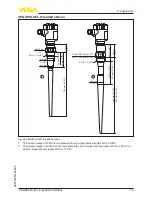
Page 74: ...40209 VEGAPULS 65 flange version 33 mm 1 30 395 mm 15 55 120 mm 4 72 270 mm 10 63 545 mm 21 46 94 mm 3 70 2 mm 0 08 Fig 45 VEGAPULS 65 flange version for sockets with 100 mm height inactive length 120...

Page 75: ...bliche Schutzrechte N here Informationen unter www vega com Les lignes de produits VEGA sont globalement prot g es par des droits de propri t intellec tuelle Pour plus d informations on pourra se r f...

Page 76: ...9 Fault rectification 52 FF parameter 68 Functional principle 9 Function blocks Analog Input AI 62 Arithmetic 67 Discret Input AI 62 Input Selector 66 Integrator 65 Output Splitter 63 PID Control 63 S...

Page 77: ...77 Notes VEGAPULS 65 Foundation Fieldbus 36518 EN 140209...

Page 78: ...78 Notes VEGAPULS 65 Foundation Fieldbus 36518 EN 140209...

Page 79: ...79 Notes VEGAPULS 65 Foundation Fieldbus 36518 EN 140209...

Page 80: ...of delivery application practical use and operat ing conditions of the sensors and processing systems correspond to the information available at the time of printing Subject to change without prior n...

Reviews: