background image

35

9 Supplement

VEGAPULS WL 61 • Profibus PA

38062-EN-140801


Ʋ Air pressure

860 … 1060 mbar/86 … 106 kPa (12.5 … 15.4 psig)

Installation reference conditions


Ʋ Min. distance to installations

> 200 mm (7.874 in)


Ʋ Reflector

Plane plate reflector


Ʋ False reflections

Biggest false signal, 20 dB smaller than the useful signal

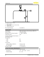
Deviation with liquids

See following diagrams

0,5 m (1.6 ft)

10 mm (0.394 in)

- 10 mm (- 0.394 in)

2 mm (0.079 in)

- 2 mm (- 0.079 in)

0

1

2

3

Fig. 36: Deviation under reference conditions
1  Reference plane

2  Antenna edge

3  Recommended measuring range

Repeatability

≤ ±1 mm

Variables influencing measurement accuracy

Temperature drift - Digital output

±3 mm/10 K relating to the max. measuring range or 

max. 10 mm

Additional deviation through electromag-

netic interference acc. to EN 61326

< ±50 mm

Characteristics and performance data

Measuring frequency

K-band (26 GHz technology)

Measuring cycle time approx.

450 ms

Step response time

1)

≤ 3 s

Beam angle

2)

10°

Emitted HF power

3)


Ʋ Average spectral transmission power 

density

-34 dBm/MHz EIRP


Ʋ Max. spectral transmission power 

density

+6 dBm/50 MHz EIRP


Ʋ Max. power density in a distance of 

1 m

< 1 µW/cm²

1)

  Time span after a sudden distance change of max. 0.5 m until the output signal reaches for the first time 90% of 

the final value (IEC 61298-2).

2)

  Outside the specified beam angle, the energy of the radar signal has a level which is reduced by 50 % (-3 dB)

3)

EIRP: Equivalent Isotropic Radiated Power

Summary of Contents for VEGAPULS WL 61

Page 1: ...Operating Instructions Radar sensor for continuous level measurement of water and wastewater VEGAPULS WL 61 Profibus PA Document ID 38062...

Page 2: ...ackaging transport and storage 9 4 Mounting 4 1 General instructions 11 4 2 Mounting versions 11 4 3 Mounting preparations mounting strap 14 4 4 Mounting instructions 14 5 Connecting to power supply 5...

Page 3: ...y instructions for Ex areas Please note the Ex specific safety information for installation and op eration in Ex areas These safety instructions are part of the operating instructions manual and come...

Page 4: ...sonnel and put into practice by them 1 3 Symbols used Information tip note This symbol indicates helpful additional information Caution If this warning is ignored faults or malfunctions can result War...

Page 5: ...instrument complying with all prevailing regulations and guidelines The instrument must only be operated in a technically flawless and reliable condition The operator is responsible for the trouble fr...

Page 6: ...proved for unrestricted use inside and outside of closed ves sels in countries of the EU and EFTA that have implemented this standard Austria Belgium Bulgaria Germany Denmark Estonia France Greece Gre...

Page 7: ...following two conditions this device may not cause interference and this device must accept any interference including interference that may cause undesired operation of the device Le pr sent appareil...

Page 8: ...ata Matrix Code for Smartphone App 13 Symbol of the device protection class 14 ID numbers instrument documentation 15 Reminder to observe the instrument documentation 16 Notified authority for CE mark...

Page 9: ...iple of operation The radar sensor VEGAPULS WL 61 is the ideal sensor for all appli cations in the water and waste water industry It is particularly suitable for level measurement in water treatment i...

Page 10: ...ansit damage or con cealed defects must be appropriately dealt with Up to the time of installation the packages must be left closed and stored according to the orientation and storage markings on the...

Page 11: ...ations of the process conditions in chapter Technical data as well as on the type label 4 2 Mounting versions Most simply mount the instrument via the straining clamp For this purpose the connection c...

Page 12: ...ables sensor mounting on e g a ceil ing wall or bracket It is available in the following versions Length 300 mm for ceiling mounting Length 170 mm for wall mounting The instrument is normally mounted...

Page 13: ...liquely 200 mm 7 87 Fig 6 Wall mounting via the mounting strap with length 170 mm Fig 7 Wall mounting with inclined wall via the mounting strap with length 300 mm For mounting the instrument on a sock...

Page 14: ...ree steps 0 90 and 180 4 4 Mounting instructions For tight installation of the version with plastic horn antenna with com pression or adapter flange the following conditions must be fulfilled 1 Use su...

Page 15: ...ee chapter Setup If you cannot maintain this distance you should carry out a false signal storage during setup This applies particularly if buildup on the vessel wall is expected In such a case it is...

Page 16: ...re that you detect the product surface not the inflowing product Fig 12 Mounting of the radar sensor with inflowing medium Approximate values of the socket heights are shown in the following illustrat...

Page 17: ...to achieve optimum measurement results Fig 14 Orientation of the sensor The mounting location of the radar sensor should be a place where no other equipment or fixtures cross the path of the microwav...

Page 18: ...should be used As an alternative sensors with guided microwave can be used These are unaffected by foam generation and are best suited for such ap plications The short examples give you introductory i...

Page 19: ...t with Khafagi Venturi flume d Min distance to sen sor hmax max filling of the flume B tightest constriction in the flume 1 Position sensor 2 Venturi flume In general the following points must be obse...

Page 20: ...s in the circuit see load values in chapter Technical data Connection is made with screened cable according to the Profibus specification Power supply and digital bus signal are carried over the same...

Page 21: ...nics Indication of the instrument type hardware and software version measurement loop name on the display or PC Indication of the status message F 105 Determine measured value on the display or PC The...

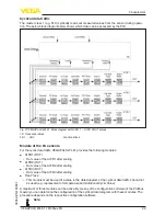
Page 22: ...ed out To perform the adjustment enter the distance with full and empty vessel see the following example 2 3 1 0 5 m 19 68 5 m 196 85 100 0 Fig 19 Parameterization example 1 Min level max meas distanc...

Page 23: ...equested values and recording conditions are set via a PC with PACTware DTM or the control system with EDD Data are thus read out and also reset Up to 500 events are automatically stored with a time s...

Page 24: ...of the status messages 1 Failure red 2 Out of specification yellow 3 Function check orange 4 Maintenance blue Failure Due to a malfunction in the instrument a failure message is outputted This status...

Page 25: ...ation Change adjustment according to the limit values difference between min and max 10 mm Bit 1 F025 Error in the lineariza tion table Index markers are not continuously rising for example illogical...

Page 26: ...within the vessel height measuring range Max measuring range of the instrument not sufficient Check or correct installation and or parameter adjustment Use an instrument with bigger measuring range Bi...

Page 27: ...tenance and provides information on causes as well as corrective measures Code Text mes sage Cause Rectification M500 Error with the reset delivery status With the reset to delivery status the data co...

Page 28: ...C with PACTware and the suitable DTM In many cases the reasons can be determined in this way and faults rectified The below tables show typical examples of application related meas urement errors with...

Page 29: ...s changed e g condensation buildup false signal suppression no longer matches Determine the reason for the changed false signals carry out false signal suppression e g with condensation Measurement er...

Page 30: ...contamination in the close range by editing 10 Measured value jumps to 100 or 0 m distance Level time 0 Level echo is no longer detected in the close range due to foam generation or false echoes in t...

Page 31: ...is also available outside normal working hours seven days a week around the clock Since we offer this service worldwide the support is provided in English The service itself is free of charge the onl...

Page 32: ...nies We use recyclable materials and have designed the parts to be easily separable Correct disposal avoids negative effects on humans and the environ ment and ensures recycling of useful raw material...

Page 33: ...ble PE hard Process fitting mounting thread on the housing Flange DIN from DN 80 ASME from 3 JIS from DN 100 10K Pipe thread cylindrical ISO 228 T1 G1 Instrument weight depending on pro cess fitting 0...

Page 34: ...ording to IEEE 754 Sensor address 126 default setting Damping 63 of the input variable 0 999 s adjustable Profibus PA profile 3 02 Number of FBs with AI function blocks with analogue input 3 Default v...

Page 35: ...perature drift Digital output 3 mm 10 K relating to the max measuring range or max 10 mm Additional deviation through electromag netic interference acc to EN 61326 50 mm Characteristics and performanc...

Page 36: ...ith resonance Shock resistance 100 g 6 ms according to EN 60068 2 27 mechanical shock Electromechanical data version IP 66 IP 68 2 bar Cable entry IP 68 cable gland Connection cable Configuration two...

Page 37: ...d They are part of the delivery or can be downloaded under www vega com VEGA Tools and Instrument search as well as under www vega com downloads and Approvals 9 2 Radio astronomy stations The followin...

Page 38: ...ent gets an unambiguous ident number ID number from the Profibus user organisation PNO This ID number is also included in the name of the GSD file Optionally to this manufacturer specific GSD file PNO...

Page 39: ...GAPULS WL 61 provides the following modules AI FB1 OUT Out value of the AI FB1 after scaling AI FB2 OUT Out value of the AI FB2 after scaling AI FB3 OUT Out value of the AI FB3 after scaling Free Plac...

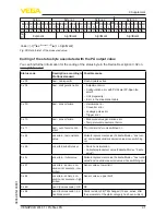
Page 40: ...EE 754 Floating point value Sta tus IEEE 754 Floating point value Sta tus IEEE 754 Floating point value Sta tus Value AI FB1 OUT AI FB1 AI FB2 OUT AI FB2 AI FB3 OUT AI FB3 Example 2 AI FB1 OUT Free Pl...

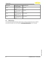
Page 41: ...nt error Configuration error with PV Scale PV Span too small Unit irregularity Error in the linearization table 0 x 0C bad sensor failure Hardware error Converter error Leakage pulse error Trigger err...

Page 42: ...x 8a good non cascade ac tive advisory alarm high limited Hi Alarm 0 x 8d good non cascade ac tive critical alarm low limited Lo Lo Alarm 0 x 8e good non cascade ac tive critical alarm high limited Hi...

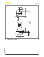
Page 43: ...GAPULS WL 61 Profibus PA 38062 EN 140801 VEGAPULS WL 61 basic version 15 mm 0 59 300 mm 11 81 42 5 mm 1 67 18 5 mm 0 73 19 mm 0 75 75 mm 2 95 72 mm 2 84 8 mm 0 32 G1 1 2 115 mm 4 53 Fig 40 VEGAPULS WL...

Page 44: ...on with mounting strap 125 mm 4 92 2 5 mm 0 10 75 mm 2 95 107 mm 4 21 115 mm 4 53 170 mm 6 69 300 mm 11 81 19 mm 0 75 98 mm 3 86 15 mm 0 59 8 5 mm 0 34 9 mm 0 35 85 mm 3 35 12 mm 0 47 9 mm 0 35 12 mm...

Page 45: ...VEGAPULS WL 61 Profibus PA 38062 EN 140801 VEGAPULS WL 61 version with compression flange 126 mm 4 96 10 5 mm 0 41 19 mm 0 75 156 mm 6 14 200 mm 7 87 21 mm 0 83 Fig 42 VEGAPULS WL 61 compression flang...

Page 46: ...PA 38062 EN 140801 VEGAPULS WL 61 version with adapter flange 2 1 15 mm 0 59 138 mm 5 43 31 mm 1 22 20 mm 0 79 8 mm 0 32 98 mm 3 86 Fig 43 VEGAPULS WL 61 adapter flange DN 100 4 JIS 100 as well as DN...

Page 47: ...che Schutzrechte N here Informationen unter www vega com Les lignes de produits VEGA sont globalement prot g es par des droits de propri t intellec tuelle Pour plus d informations on pourra se r f rer...

Page 48: ...lume 19 Rectangular flume 18 Foam generation 18 Functional principle 9 G GSD file 38 I Inflowing medium 16 Installation position 15 Instrument master file 38 M Measured value memory 23 Mounting Angle...

Page 49: ...49 Notes VEGAPULS WL 61 Profibus PA 38062 EN 140801...

Page 50: ...50 Notes VEGAPULS WL 61 Profibus PA 38062 EN 140801...

Page 51: ...51 Notes VEGAPULS WL 61 Profibus PA 38062 EN 140801...

Page 52: ...of delivery application practical use and operat ing conditions of the sensors and processing systems correspond to the information available at the time of printing Subject to change without prior n...

Reviews: