background image

O

perating

I

nstructions

VEGASON

63

4

...

20

m

A

/

HART

U

ltrasonic

Summary of Contents for VEGASON 63

Page 1: ...Operating Instructions VEGASON 63 4 20 mA HART Ultrasonic...

Page 2: ...guration 10 3 2 Principle of operation 11 3 3 Operation 11 3 4 Packaging transport and storage 12 4 Mounting 4 1 General instructions 13 4 2 Mounting instructions 15 5 Connecting to power supply 5 1 P...

Page 3: ...stment with AMS and PDM 45 7 5 Saving the parameter adjustment data 45 8 Maintenance and fault recti cation 8 1 Maintenance 46 8 2 Remove interferences 46 8 3 Exchange of the electronics module 48 8 4...

Page 4: ...nuals are listed in section Product description Operating instructions manuals for accessories and replacement parts Tip To ensure reliable setup and operation of your VEGASON 63 we o er accessories a...

Page 5: ...se personnel and put into practice by them 1 3 Symbolism used Information tip note This symbol indicates helpful additional information Caution If this warning is ignored faults or malfunc tions can r...

Page 6: ...high tech instrument requiring the strict observance of standard regulations and guidelines The user must take note of the safety instructions in this operating instructions manual the country speci c...

Page 7: ...vailable functions depends on the respective software version of the individual components The software version of VEGASON 63 can be determined as follows l via PACTware l on the type label of the ele...

Page 8: ...n by electrostatic charges is to be expected Transducer process tting and housing as the case may be depending on instrument version are made of electrically non conductive plastic l Make sure that th...

Page 9: ...ting instructions manual 2 11 Environmental instructions Protection of the environment is one of our most important duties That is why we have introduced an environment management system with the goal...

Page 10: ...ions manual Plug connector for continuously measuring sensors optional if necessary further certi cates VEGASON 63 consists of the following components l Process tting with transducer l Housing with e...

Page 11: ...ta in the Supplement The backlight of the indicating and adjustment module is powered by the sensor The prerequisite for this is a supply voltage at a certain level The exact voltage speci cations are...

Page 12: ...e of these instruc tions can cause damage to the device The delivery must be checked for completeness and possible transit damage immediately at receipt Ascertained transit damage or concealed defects...

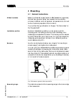
Page 13: ...tall the indicating and adjustment module in four di erent positions each displaced by 90 Use the recommended cables see chapter Connecting to power supply and tighten the cable gland You can give you...

Page 14: ...ical data in the Supplement 1 2 Fig 3 Min distance to the max level 1 Dead zone 2 Reference plane Information If the medium reaches the transducer buildup can form on it and cause faulty measurements...

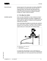
Page 15: ...iple echoes can arise These can however be faded out by an appropriate adjustment see Setup If you cannot keep this distance you should carry out a false echo memory before setup This applies mainly i...

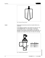
Page 16: ...a socket piece You will nd recommended values for socket heights in the following illustration The socket end should be smooth and burr free if possible also rounded Then carry out a false echo storag...

Page 17: ...a swivelling holder mounting strap can be implemented Fig 9 Orientation in solids To reduce the min distance to the medium you can also mount VEGASON 63 with a beam de ector By doing this it is possi...

Page 18: ...echo storage should be carried out during setup If large vessel installations such as struts or supports cause false echoes these can be attenuated through supplementary measures Small inclined sheet...

Page 19: ...in the vessel dense foams which considerably damp the emitted signals may form on the product surface If foams are causing measurement errors the sensor should be used in a standpipe or alternatively...

Page 20: ...ons foam generation and turbulence is excluded Standpipes must extend all the way down to the requested min level as measurement is only possible within the tube max min 1 Fig 14 Standpipe in tank 1 V...

Page 21: ...Ex VEGAS TAB 690 as well as all VEGAMETs meet this requirement Bear in mind the following factors regarding supply voltage l Output voltage of the power supply unit can be lower under nominal load wit...

Page 22: ...interference signals remains Take note of the corresponding installation regulations for Ex applications In particular make sure that no potential equal isation currents ow over the cable screen In ca...

Page 23: ...pression nut of the cable entry The seal ring must completely encircle the cable 12 Screw the housing cover back on The electrical connection is nished 5 3 Wiring plan single chamber housing 1 4 4 4 2...

Page 24: ...s for connection of the external indication VEGADIS 61 3 Ground terminal for connection of the cable screen 4 Spring loaded terminals for voltage supply I2C Display 1 1 2 5 6 7 8 Fig 18 Wiring plan si...

Page 25: ...blind stopper with version IP 66 IP 68 1 bar1 5 Cable entry or plug 1 3 2 Display 1 2 5 6 7 8 I2C Fig 20 Electronics compartment double chamber housing 1 Plug connector for VEGACONNECT I C interface...

Page 26: ...ECT I C interface 2 Ground terminal for connection of the cable screen 3 Spring loaded terminals for voltage supply I2C 1 1 2 Fig 22 Wiring plan double chamber housing 1 Voltage supply Signal output C...

Page 27: ...rox 30 seconds l Internal check of the electronics l Indication of the instrument type the rmware as well as the sensor TAGs sensor designation l Output signal jumps brie y approx 10 seconds to the se...

Page 28: ...ation This function is for instruments with StEx WHG or ship approval as well as country speci c approvals such as those according to FM or CSA available at a later date Note You will nd detailed info...

Page 29: ...tional connection is not necessary Fig 24 Installation of the indicating and adjustment module Note If you intend to retro t VEGASON 63 with an indicating and adjustment module for continuous measured...

Page 30: ...pt input jump to the next higher menu The sensor is adjusted via the four keys of the indicating and adjustment module The LC display indicates the individual menu items The functions of the individua...

Page 31: ...level displayed an allocation of the measured distance to the percentage height must be made To carry out this adjustment the distance is entered with full and empty vessel If these values are not kno...

Page 32: ...nd set the cursor to the requested position with Set the requested percentage value with and save with OK The cursor jumps now to the distance value 4 Enter the appropriate distance value in m corresp...

Page 33: ...s with bad re ective properties is considerably increased Enter the requested parameter via the appropriate keys save your settings and jump to the next menu item with the key Apart from the medium th...

Page 34: ...percent but e g in l or kg a scaling can be also set in the menu item Display Linearisation curve linear Enter the requested parameter via the appropriate keys save your settings and jump to the next...

Page 35: ...are detected by the sensor and saved after con rming with OK Note Check the distance to the product surface because if an incorrect too large value is entered the existing level will be saved as false...

Page 36: ...not known Damping 0 s Linearization linear Sensor TAG Sensor Displayed value Distance Current output characteristics 4 20 mA Current output max current 20 mA Current output min current 4 mA Current o...

Page 37: ...lation or trend curve presentation are shown in the following menu schematic You will nd a detailed description of these menu items in the operating instructions manual Indicating and adjustment modul...

Page 38: ...000 m d 2 000 m d 1 3 Medium Liquid 1 4 Vessel form Storage tank 1 5 Damping 0 s 1 6 Linearisation curve linear 1 7 Sensor TAG Sensor Display 2 Basic adjustment Display Diagnostics Service Info 2 1 Di...

Page 39: ...l mode 3 6 mA Min current 3 8 mA 4 4 Simulation Start simulation 4 5 Reset Select reset 4 6 Unit of measurement m d select 4 7 Language Deutsch 4 8 HART mode Standard Address 0 4 9 Copy sensor data Co...

Page 40: ...o indicating and adjustment module The procedure is described in the operating instructions manual Indicating and adjustment module in the menu item Copy sensor data The data remain there permanently...

Page 41: ...terface directly on the sensor 1 RS232 connection 2 VEGASON 63 3 I C adapter cable for VEGACONNECT 3 Necessary components l VEGASON 63 l PC with PACTware and suitable VEGA DTM l VEGACONNECT 3 with I C...

Page 42: ...pprox 250 Ohm l Power supply unit Note With power supply units with integrated HART resistance internal resistance approx 250 Ohm an additional external resistance is not necessary This applies e g to...

Page 43: ...tly to the sensor 1 I C bus Com interface 2 I C connection cable of VEGACONNECT 4 Necessary components l VEGASON 63 l PC with PACTware and suitable VEGA DTM l VEGACONNECT 4 l Power supply unit or proc...

Page 44: ...sary This applies e g to the VEGA instruments VEGATRENN 149A VEGADIS 371 VEGAMET 381 Also usual Ex separators are most of the time equipped with a su cient current limitation resistor In such cases VE...

Page 45: ...s AMS and PDM are available as DD or EDD The instrument descriptions are already implemented in the current versions of AMS and PDM For older versions of AMS and PDM a free of charge download is avail...

Page 46: ...le DTM In many cases the causes can be determined in this way and faults can be recti ed However should these measures not be successful call the VEGA service hotline in urgent cases under the phone n...

Page 47: ...tions for the wiring of intrinsically safe circuits must be observed E013 l no measured value available sensor in boot phase sensor does not nd an echo e g because of faulty installation or incorrect...

Page 48: ...from the Internet see operating instructions manual Oscillator The oscillators are adapted to the respective sensor and di er also in the signal output or power supply The suitable oscillator is list...

Page 49: ...form and if need be also a safety data sheet outside on the packaging l Please ask the agency serving you for the address of your return shipment You can nd the respective agency on our website www ve...

Page 50: ...o be easily separable WEEE directive 2002 96 EG This instrument is not subject to the WEEE directive 2002 96 EG and the respective national laws in Germany e g ElektroG Pass the instrument directly on...

Page 51: ...pection window in housing cover Polycarbonate Ground terminal 316Ti 316L Weight 2 7 5 7 kg 6 12 6 lbs depending on the process tting and housing Output variable Output signal 4 20 mA HART Signal resol...

Page 52: ...tal plate 2x2 m 6 56x6 56 ft False re ections Biggest false echo 20 dB smaller than the useful echo Measuring characteristics Ultrasonic frequency 35 kHz Interval 2 s dependent on the parameter adjust...

Page 53: ...ft 9 843 ft 0 394 in 0 787 in 1 181 in 0 236 in 0 236 in 0 394 in 0 787 in 1 181 in Fig 32 Deviation VEGASON 63 in Inch measuring range in ft In uence of the ambient temperature to the sensor electron...

Page 54: ...or l 1x closing cap NPT 1x blind plug NPT or l 1x plug depending on the version 1x blind plug M20x1 5 Double chamber housing l 1x cable entry M20x1 5 cable 5 9 mm 1x blind stopper M20x1 5 1x blind st...

Page 55: ...meter approx 8 mm 0 315 in Colour standard PE Black Colour standard PUR Blue Colour Ex version Blue Indicating and adjustment module Power supply and data transmission through the sensor Indication LC...

Page 56: ...IP 66 IP 67 Alu and stainless steel standard IP 66 IP 68 0 2 bar 12 Alu and stainless housing optionally available IP 66 IP 68 1 bar Overvoltage category III Protection class II Functional safety SIL...

Page 57: ...Approvals13 Ship approvals GL LRS ABS CCS RINA DNV 13 Deviating data in Ex applications see separate safety instructions Supplement VEGASON 63 4 20 mA HART 57 28777 EN 070507...

Page 58: ...odule the housing is 9 mm 1 64 higher 1 Plastic housing 2 Stainless steel housing 3 Aluminium double chamber housing 4 Aluminium housing Housing in protection IP 66 IP 68 1 bar 117mm 4 39 64 116mm 4 9...

Page 59: ...VEGASON 63 dimension L with Alu housing 118 mm 4 41 64 dimension L with plastic and stainless steel housing 113 mm 4 29 64 1 Mounting strap 2 Compression ange 3 Dead zone 0 6 m 2 ft 4 Measuring range...

Page 60: ...es lignes de produits VEGA sont globalement prot g es par des droits de propri t intellectuelle Pour plus d informations on pourra se r f rer au site http www vega com VEGA lineas de productos est n p...

Page 61: ...Supplement VEGASON 63 4 20 mA HART 61 28777 EN 070507...

Page 62: ...Supplement 62 VEGASON 63 4 20 mA HART 28777 EN 070507...

Page 63: ...Supplement VEGASON 63 4 20 mA HART 63 28777 EN 070507...

Page 64: ...om www vega com ISO 9001 All statements concerning scope of delivery application practical use and operating conditions of the sensors and processing systems correspond to the information avail able a...

Reviews: