background image

24

7 Maintenance and fault rectification

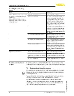
VEGASWING 61 • - transistor (NPN/PNP)

29225-EN-161125

Error

Reason

Removal

VEGASWING 61 signals "covered" 

without being submerged (overfill 

protection)
VEGASWING 61 signals "uncov-

ered" when being submerged (dry 

run protection)

Operating voltage too low

Check operating voltage

Electronics defective

Press the mode switch. If the instru-

ment then changes the mode, the 

vibrating element may be covered 

with buildup or mechanically dam-

aged. Should the switching function 

in the correct mode still be faulty, re-

turn the instrument for repair.
Press the mode switch. If the in-

strument then does not change the 

mode, the electronics module may 

be defective. Exchange the electron-

ics module.

Unfavourable installation location

Mount the instrument at a location in 

the vessel where no dead zones or 

air bubbles can form.

Buildup on the vibrating element

Check the vibrating element and the 

sensor for buildup and remove the 

buildup if there is any.

Wrong mode selected

Set the correct mode with the mode 

switch (overflow protection, dry run 

protection). Wiring should be carried 

out according to the closed-circuit 

principle.

Signal lamp flashes red

Error on the vibrating element

Check if the vibrating element is 

damaged or extremely corroded.

Interference on the electronics mod-

ule

Exchanging the electronics module

instrument defective

Exchange the instrument or send it 

in for repair

Depending on the reason for the fault and the measures taken, the 

steps described in chapter "

Set up

" may have to be carried out again.

7.3  Exchanging the electronics

If the electronics module is defective, it can be replaced by the user.
In Ex applications only an electronics module with respective Ex ap-

proval may be used.
You can find all the information you need to carry out an electronics 

exchange in the handbook of the new electronics module.
In general, all electronics modules of series SW60 can be inter-

changed. If you want to use an electronics module with a different 

signal output, you carry out the complete setup. You find the neces-

sary, suitable operating instruction on our homepage.

Checking the switching 

signal

Reaction after fault recti-

fication

Summary of Contents for VEGASWING 61

Page 1: ...Operating Instructions Vibrating level switch for liquids VEGASWING 61 transistor NPN PNP Document ID 29225...

Page 2: ...Adjustment 8 3 4 Storage and transport 9 3 5 Accessories 9 4 Mounting 4 1 General instructions 11 4 2 Mounting instructions 14 5 Connecting to power supply 5 1 Preparing the connection 16 5 2 Connecti...

Page 3: ...Safety instructions for Ex areas Take note of the Ex specific safety instructions for Ex applications These instructions are attached as documents to each instrument with Ex approval and are part of t...

Page 4: ...This symbol indicates helpful additional information Caution If this warning is ignored faults or malfunctions can result Warning If this warning is ignored injury to persons and or serious damage to...

Page 5: ...opriate or incorrect use of the instrument can give rise to application specific hazards e g vessel overfill or damage to system components through incorrect mounting or adjustment 2 4 General safety...

Page 6: ...ther information in the Safety Manual VEGASWING series 60 2 8 Safety instructions for Ex areas Please note the Ex specific safety information for installation and op eration in Ex areas These safety i...

Page 7: ...the components Housing lid Housing with electronics Process fitting with tuning fork 1 2 3 Fig 1 VEGASWING 61 1 Housing lid 2 Housing with electronics 3 Process fitting The type label contains the mo...

Page 8: ...condition i e the output is open safe state The tuning fork is piezoelectrically energised and vibrates at its mechanical resonance frequency of approx 1200 Hz The piezos are fixed mechanically and ar...

Page 9: ...ion the packages must be left closed and stored according to the orientation and storage markings on the outside Unless otherwise indicated the packages must be stored only under the following conditi...

Page 10: ...10 3 Product description VEGASWING 61 transistor NPN PNP 29225 EN 161125 The following plug connectors are available M12 x 1 ISO 4400 Harting HAN 7D Harting HAN 8D Amphenol Tuchel...

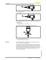
Page 11: ...int with vertical mounting The switching point applies to water in conjunction with the basic setting of the density switch 0 7 g cm 0 025 lbs in When mounting VEGASWING 61 make sure that this marking...

Page 12: ...k position with flange versions 1 Marking with flange version facing up Use the recommended cables see chapter Connecting to power supply and tighten the cable gland You can give your instrument addit...

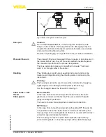
Page 13: ...st be treated accordingly Bending the vibrating element will destroy the instrument Warning The housing must not be used to screw the instrument in Applying tightening force can damage internal parts...

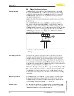
Page 14: ...us products the surfaces of the tuning fork should be vertical in order to reduce buildup on the tuning fork On the screwed version you will find a marking on the hexagon With this you can check the p...

Page 15: ...leakage of the medium The service life of the gas tight leadthrough depends on the chemical resistance of the materials See Technical data Caution If it is determined e g via an error message from VEG...

Page 16: ...tal lation regulations for hazardous areas must be given priority The data for power supply are specified in chapter Technical data The instrument is connected with standard two wire cable without scr...

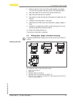
Page 17: ...he wires in the terminals by lightly pulling on them 9 Tighten the compression nut of the cable entry gland The seal ring must completely encircle the cable 10 Screw the housing lid back on The electr...

Page 18: ...ch for switching point adaptation 4 Ground terminal 5 Connection terminals We recommend connecting VEGASWING 61 in such a way that the switching circuit is open when there is a level signal line break...

Page 19: ...ig 11 PNP action 5 4 Wiring plan version IP 66 IP 68 1 bar 1 2 3 4 5 Fig 12 Wire assignment connection cable The numbers of the wires corre spond to the terminals of the instrument 1 brown voltage sup...

Page 20: ...ts Signal lamp 1 DIL switch for mode adjustment A B 2 DIL switch for sensitivity adjustment 3 Note Always immerse the tuning fork of VEGASWING 61 in a liquid to test its function Do not test the funct...

Page 21: ...n In products with a different density the switching point will shift in the direction of the housing or tuning fork end depending on the density and type of installation Note Keep in mind that foams...

Page 22: ...22 6 Setup VEGASWING 61 transistor NPN PNP 29225 EN 161125 Level Switching status Control lamp Fault any open flashes red...

Page 23: ...sed by the following e g Sensor Process Voltage supply Signal processing The first measure to take is to check the output signal In many cases the causes can be determined this way and the faults quic...

Page 24: ...ected Set the correct mode with the mode switch overflow protection dry run protection Wiring should be carried out according to the closed circuit principle Signal lamp flashes red Error on the vibra...

Page 25: ...bout the procedure in the download area of our homepage www vega com By doing this you help us carry out the repair quickly and without hav ing to call back for needed information If a repair is neces...

Page 26: ...an be recycled by spe cialised recycling companies We use recyclable materials and have designed the parts to be easily separable WEEE directive 2002 96 EG This instrument is not subject to the WEEE d...

Page 27: ...mm 0 839 in 316L Alloy C22 2 4602 316L with ECTFE coating 316L with PFA coating Materials non wetted parts Plastic housing plastic PBT Polyester Aluminium die cast housing Aluminium die casting AlSi10...

Page 28: ...3852 A G G1 American pipe thread conical ASME B1 20 1 NPT 1 NPT Flanges DIN from DN 25 ASME from 1 hygienic fittings Slotted nut DN 40 PN 40 Clamp 1 DIN 32676 ISO 2852 316L Clamp 2 DIN 32676 ISO 2852...

Page 29: ...Product density 1 g cm 0 036 lbs in water Product viscosity 1 mPa s Superimposed pressure 0 kPa Sensor installation Vertically from top Density selection switch 0 7 g cm Measuring accuracy Deviation 1...

Page 30: ...g cm 0 018 lb in 4 Switch position 0 7 g cm 0 025 lb in 5 Switching point at reference conditions notch 6 Tuning fork Influence of the process pressure to the switching point 1 2 3 4 12 174 1 38 551 1...

Page 31: ...ured up to an operating pressure of 100 bar 10000 kPa 1450 psig at a maximum process temperature of 50 C 122 F only with threaded versions Process temperature thread or flange temperature VEGASWING 61...

Page 32: ...C 392 F 250 C 482 F 20 290 1 14 5 40 580 64 928 Fig 29 Process temperature Process pressure with switch position 0 5 g cm sensitivity switch 1 Process pressure in bar psig 2 Process temperature in C...

Page 33: ...x 1 5 or 1 x closing cap NPT 1 x blind plug NPT Connection cable Wire cross section 0 5 mm AWG 20 Wire resistance 0 036 m 0 011 ft Tensile strength 1200 N 270 lbf Standard length 5 m 16 4 ft Max lengt...

Page 34: ...with approvals can have different technical specifications depending on the version For that reason the associated approval documents of these instruments have to be carefully noted They are part of t...

Page 35: ...rotection rating IP 66 IP 68 1 bar 1 Stainless steel housing precision casting 2 Aluminium housing VEGASWING 61 G A NPT G1A 1 NPT 18 5 mm 0 73 32 G A NPT 41 G1A 1 NPT 57 mm 2 24 50 mm 1 97 33 7 mm 1 3...

Page 36: ...36 9 Supplement VEGASWING 61 transistor NPN PNP 29225 EN 161125 VEGASWING 61 options 34 mm 1 34 178 mm 7 01 1 2 Fig 33 Options 1 Gas tight leadthrough 2 Temperature adapter...

Page 37: ...nen unter www vega com Les lignes de produits VEGA sont globalement prot g es par des droits de propri t intellec tuelle Pour plus d informations on pourra se r f rer au site www vega com VEGA lineas...

Page 38: ...38 Notes VEGASWING 61 transistor NPN PNP 29225 EN 161125...

Page 39: ...39 Notes VEGASWING 61 transistor NPN PNP 29225 EN 161125...

Page 40: ...of delivery application practical use and operat ing conditions of the sensors and processing systems correspond to the information available at the time of printing Subject to change without prior n...

Reviews: