29
6 Setup
VEGASWING 63 • Two-wire 8/16 mA
29232-EN-180704
Note:
Keep in mind that the starting time t
A
of the voltage supply can extend
the time up to the first switching (e.g. VEGATOR 636: +1 s)
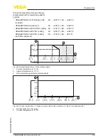
Test procedure
After releasing the button or after a brief line break.
Sensor
current -
Sensor
Level relay
A - overfill
protection
Signal lamp
A - Overfill
protection
Level relay
B - dry run
protection
Signal lamp
B - Dry run
protection
Fail safe
relay
Control
lamp
1. Fault sig-
nal
0.6 s
(±0,2 s)
+ t
A
1)
< 3.6 mA
currentless
currentless
currentless
2. Empty
signal
1.5 s
(±0.5 s)
8 mA
(±1.5 mA)
energized
currentless
energized
3. Full signal
1.5 s
(±0.5 s)
16 mA
(±1.5 mA)
currentless
energized
energized
4. Return
to current
operating
condition
-
-
-
-
-
-
Test assessment (SPLC)
Test passed
Status
Current value
Time
False signal
< 3.6 mA
0.6 s (±0.2 s)
Uncovered
8 mA (±1.5 mA)
1.5 s (±0.5 s)
Covered
16 mA (±1.5 mA) 1.5 s (±0.5 s)
This test is valid if you cannot change the vessel filling or cannot
dismount the sensor.
With the VEGATOR 121 or 122 signal conditioning instrument, the
test result can be checked directly on an LED on the signal condition-
ing instrument.
This is the most comfortable and simple way to carry out the test.
A test key is lowered in the front plate of the VEGATOR 121, 122
signal conditioning instrument. Push the test key for > 2 seconds with
a suitable object. Hence a test is started. The sensor must neither be
dismounted nor triggered by filling the vessel.
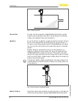
4 Test key on the signal
conditioning instrument
VEGATOR 121, 122
1)
Starting time of the voltage supply


