17
6 Setup
VEGATOR 121 •
57662-EN-210714
3,6
8
16
on
off
t
t
t
mA
off
on
1
2
3
4
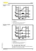
Fig. 4: Flow chart of a correct switching-on impulse
1 Level relay
2 Fail safe relay
3 Interruption of the sensor current for at least 1 s
4 Time until event is available (at least 6 s)
t
t
t
3,6
8
16
mA
off
on
on
off
3
4
2
1
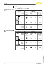
Fig. 5: Flow chart of an incorrect switching-on impulse
1 Level relay
2 Fail safe relay
3 Interruption of the sensor current for at least 1 s
4 Time until event is available (at least 6 s)
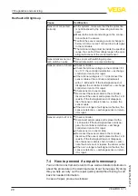
6.4 Function table "Point level"
The following table provides an overview of the switching conditions
depending on the set mode and the level.
Switching-on impulse
correct
Switching-on impulse
incorrect


