background image

2

F

or your safety

2

.

1

A

uthorised personnel

A

ll operations described in this operating instructions manual must be

carried out only by trained specialist personnel authorised by the plant
operator

.

D

uring work on and with the device the required personal protective

equipment must always be worn

.

2

.

2

A

ppropriate use

VEGATOR

631

E

x is a universal signal conditioning instrument for

connection of a level switch

.

Y

ou can

nd detailed information on the application range in chapter

"

P

roduct description

"

.

O

perational reliability is ensured only if the instrument is properly used

according to the speci

cations in the operating instructions manual as

well as possible supplementary instructions

.

F

or safety and warranty reasons

,

any invasive work on the device

beyond that described in the operating instructions manual may be
carried out only by personnel authorised by the manufacturer

.

A

rbitrary

conversions or modi

cations are explicitly forbidden

.

2

.

3

W

arning about misuse

I

nappropriate or incorrect use of the instrument can give rise to

application

-

speci

c hazards

,

e

.

g

.

vessel over

ll or damage to system

components through incorrect mounting or adjustment

.

2

.

4

G

eneral safety instructions

T

his is a high

-

tech instrument requiring the strict observance of

standard regulations and guidelines

.

T

he user must take note of the

safety instructions in this operating instructions manual

,

the country

-

speci

c installation standards as well as all prevailing safety

regulations and accident prevention rules

.

T

he instrument must only be operated in a technically

awless and

reliable condition

.

T

he operator is responsible for trouble

-

free

operation of the instrument

.

D

uring the entire duration of use

,

the user is obliged to determine the

compliance of the required occupational safety measures with the
current valid rules and regulations and also take note of new
regulations

.

VEGATOR

631

E

x

S

ignal conditioning instrument

5

2

F

or your safety

23440

-

EN

-

090130

Summary of Contents for VEGATOR 631 Ex

Page 1: ...Operating Instructions VEGATOR 631 Ex Signal conditioning instrument Signal conditioning instruments and communication in out...

Page 2: ...ion 8 3 4 Packaging transport and storage 8 4 Mounting 4 1 General instructions 10 4 2 Mounting instructions 10 5 Connecting to power supply 5 1 Preparing the connection 13 5 2 Connection procedure 13...

Page 3: ...ion Information Supplementary documents appropriate to the ordered version come with the delivery You can nd them listed in chapter Product description VEGATOR 631 Ex Signal conditioning instrument 3...

Page 4: ...ractice by them 1 3 Symbolism used Information tip note This symbol indicates helpful additional information Caution If this warning is ignored faults or malfunctions can result Warning If this warnin...

Page 5: ...cturer Arbitrary conversions or modi cations are explicitly forbidden 2 3 Warning about misuse Inappropriate or incorrect use of the instrument can give rise to application speci c hazards e g vessel...

Page 6: ...rating instructions manual and come with the Ex approved instruments 2 7 Environmental instructions Protection of the environment is one of our most important duties That is why we have introduced an...

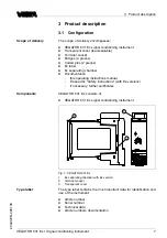
Page 7: ...ssary further certi cates VEGATOR 631 Ex consists of l VEGATOR 631 Ex signal conditioning instrument 3 1 2 1 2 3 4 5 6 7 8 9 10 11 12 13 14 631Ex on 0 10 5 Fig 1 VEGATOR 631 Ex 1 Ex separating chamber...

Page 8: ...Packaging transport and storage Your instrument was protected by packaging during transport Its capacity to handle normal loads during transport is assured by a test according to DIN EN 24180 The pack...

Page 9: ...sed to corrosive media l Protected against solar radiation l Avoiding mechanical shock and vibration l Storage and transport temperature see chapter Supplement Technical data Ambient conditions l Rela...

Page 10: ...ected mounting outside the switching cabinet we o er an insulated protective housing with transparent cover IP 65 for surface mounting In this housing you can mount a maximum of 3 instruments of 36 mm...

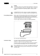
Page 11: ...and the EG type approval certi cate are observed VEGATOR 631 Ex must not be opened Close the upper terminals according to the following illustration 1 2 4 3 Fig 3 Mounting the separating chamber All...

Page 12: ...1 1 4 2 3 Fig 4 Plug in socket VEGATOR 631 Ex 1 Ex separating chamber 2 Ex coding with Ex version A 3 Type coding for VEGATOR 631 Ex 3 4 Bridges for looping the operating voltage 12 VEGATOR 631 Ex Sig...

Page 13: ...61326 for industrial areas screened cable should be used From a cable length of 50 m use one cable for each signal conditioning instrument If you are using a common cable the min and max cables must...

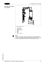
Page 14: ...oding must also be inserted correctly 5 3 Wiring plan 1 2 5 4 1 3 2 4 5 6 9 13 10 14 12 7 8 L N 1 2 3 6 Fig 5 Limit level measurement 1 Relay output 2 Power supply 3 Transistor output 4 Mass 5 max 6 P...

Page 15: ...in 7 Probe e g EL3 Note Mutiple rod probes connected to several signal conditioning instru ments or to a multiple channel instrument need a ground rod to keep the signal conditioning instruments from...

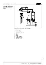
Page 16: ...rol with over ll protection 1 Relay output 2 Power supply 3 Transistor output 4 Max over ll protection 5 Min 6 Max 7 Mass 8 Probe e g EL3 A Over ll protection B Min max control Two point control min m...

Page 17: ...VEGATOR 631 Ex 2 VEGATOR 631 Ex 3 PLC The resistor RS serves as short circuit protection RS P 47 0 25 W 150 0 75 W 330 1 5 W 560 2 2 W Circuit of the transistor outputs VEGATOR 631 Ex Signal condition...

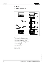
Page 18: ...ments 1 Control lamp Fault signal LED red 2 Potentiometer for switching point adjustment 3 Control lamp Output LED yellow 4 Control lamp Power supply LED green 5 Bridge for adjusting the fault signal...

Page 19: ...nt cover 6 2 Adjustment elements Control lamps LED in the front plate indicate operation switching status and fault signal l Green Operating control lamp Mains voltage on instrument is operating l Red...

Page 20: ...ration time 6 s l 4 Integration time 12 s With switch 1 you can adjust the mode A over ll protection or B dry run protection 1 2 3 4 12 6 2 A B off sec t Fig 11 DIL switch block In the example see pre...

Page 21: ...a fault message is not wanted a bridge must be provided on the signal conditioning instrument instead of the resistor in the connection housing of the probe Note The line monitoring and the fault sig...

Page 22: ...n set mode A or B by means of the selection switch Mode A Preferrably as over ow protection compulsory as over ll protection 1 2 3 Fig 14 Mode A Over ll protection Means with covered max electrode l R...

Page 23: ...and the momenet when the switching function is triggered there is an integration time of 0 5 sec The potentionmeter must therefore be turned slowly A possible additional integration time should only b...

Page 24: ...nductivity of the medium i e the relay deenergises at max level and the transistor blocks This switching condition remains until the level falls below the position of the min electrode i e the relay e...

Page 25: ...The relay deenergises again at max level and the transistor blocks VEGATOR 631 Ex Signal conditioning instrument 25 6 Set up 23440 EN 090130...

Page 26: ...he support is only available in the English language The service is free of charge only the standard telephone costs will be charged The red failure control lamp LED of the signal conditioning instrum...

Page 27: ...certi cates Repair form By doing this you help us carry out the repair quickly and without having to call back for needed information l Print and ll out one form per instrument l Clean the instrument...

Page 28: ...E directive 2002 96 EG and the respective national laws Pass the instrument directly on to a specialised recycling company and do not use the municipal collecting points These may be used only for pri...

Page 29: ...onitoring 220 k Measuring circuit max 5 V e max 1 mA Permissible line capacitance 1 x 100 nF or 2 x 70 nF with min max control Switching hysteresis 15 Adjustment elements DIL switch block for preadjus...

Page 30: ...temperature 40 70 C 40 158 F Electromechanical data Screw terminals for wire cross section up to 1 5 mm AWG 16 Electrical protective measures Protection class Signal conditioning instrument IP 30 Ter...

Page 31: ...5 mm 2 15 5 6 7 8 9 10 12 13 14 1 2 on 3 Fig 16 Dimensions VEGATOR 631 Ex 1 Transparent cover 2 Carrier rail 35 x 7 5 or 35 x 15 according to EN 50022 3 Ex separating chamber VEGATOR 631 Ex Signal co...

Page 32: ...vega com Printing date ISO 9001 All statements concerning scope of delivery application practical use and operating conditions of the sensors and processing systems correspond to the information avail...

Reviews: