background image

© Hydro-Hot

®

 Hydronic Heating System Owner’s Manual / Manuel du 

proprié

taire du système de chauffage Hydronic Hydro-Hot

®

  09/05

Page  15

Low Tank Level Cutoff Indicator Light:

This indicator light will illuminate RED when either the 120 

Volt-AC Electric Heating Element and/or Diesel-Burner have 

automatically shut down due to a low antifreeze and water 

heating solution level inside the Hydro-Hot’s Boiler Tank.  

This fault will automatically reset when the low level  

condition is corrected.

Low Battery Voltage Fault Indicator Light:

This indicator light will illuminate RED whenever the VDC 

voltage level is too low for the Hydro-Hot to operate  

properly.  This fault must be manually reset after the voltage 

level has been restored to the VDC battery system; reference 

the 

Low Voltage 

information below.

Low Voltage Fault Indicator Light and Reset Button:

The Hydro-Hot’s Electronic Controller must be manually 

reset whenever the Low Battery Voltage Fault indicator light 

has been activated.  The Electronic Controller can be reset 

either by pressing the “Low Voltage Reset” button located 

on the Electronic Controller (use a thin, straight, nonmetallic 

object to access the reset button through the small hole in the  

faceplate) or by turning 

OFF

 the Diesel switch on the Heater’s 

TROUBLESHOOTING

Interior Switch Panel for approximately 30 seconds, then  

turning the switch back 

ON

.

Overload Fault Indicator Light:

This indicator light will illuminate RED whenever one of the 

following conditions have occurred:

A. 

The Hydro-Hot is off due to an electrical overload (i.e., 

short) in the main VDC power supply circuitry.

B.

  The Hydro-Hot is off due to a combination of high electri-

cal VDC power loads and a high surface temperature of 

the Electronic Controller.

The Hydro-Hot will automatically restart once the electrical 

overload (i.e., short) and/or high-heat condition is corrected.

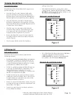
Heating Zones Status Indicator Lights:

These five indicator lights (separately) will illuminate GREEN 

whenever a Zone Thermostat, for each particular zone, is  

calling for heat.  The GREEN indicator lights also indicate 

that VDC power is being supplied to the particular interior 

heating zone’s Heat Exchangers (i.e., fan motors).  If any of 

Voyant « Low Tank-Level Cutoff » (Interrupteur de bas 

niveau dans la chaudière) :

Ce voyant s’allumera en ROUGE si l’élément de chauffage 

électrique à 120 Vca s’est éteint ou si le brûleur diesel s’est 

arrêté automatiquement dû à un faible niveau de la solution de 

chauffage d’antigel et d’eau dans la chaudière du Hydro-Hot. 

Cette alarme s’éteindra automatiquement lorsque le niveau de la 

solution sera rétabli.

Voyant « Low Battery Voltage Fault » (Basse tension de 

l’accumulateur) :

Ce voyant s’allume en ROUGE lorsque l’alimentation en 

courant continu offre une tension trop faible pour permettre au 

Hydro-Hot de fonctionner correctement. Cette alarme devra être 

rappelée manuellement lorsque la tension du courant continu a 

été rétabli. Voir « bouton Low Voltage Reset » au paragraphe 

qui suit.

Voyant « Low Battery Voltage Fault » (Basse tension de 

l’accumulateur) et bouton « Low Voltage Reset » (Bouton de 

réinitialisation basse tension) : 

Le contrôle électronique du Hydro-Hot doit être réinitialisé 

manuellement à chaque fois que le voyant Low Battery Voltage 

Fault s’est allumé. Le contrôle électronique peut être réinitialisé 

en pressant le bouton Low Voltage Reset situé sur le devant 

du contrôle électronique (utilisez un objet mince, droit et non 

DÉPANNAGE

métallique pour accéder au bouton par le petit orifice sur le 

panneau avant) ou en mettant l’interrupteur DIESEL qui est 

situé sur le panneau de commande intérieur à 

OFF

 pendant 

environ 30 secondes, puis en le remettant à 

ON

.

Voyant « Overload fault » (Panne de surcharge) :

Ce voyant s’allume en ROUGE lorsqu’une des conditions 

suivantes se produit :

A. 

Le Hydro-Hot s’est éteint dû à une surcharge électrique 

(court-circuit) sur l’alimentation en courant continu.

B.

  Le Hydro-Hot s’est éteint dû à une combinaison de 

charge élevée sur l’alimentation électrique en courant 

continu et une température élevée à la surface du contrôle 

électronique.

Le Hydro-Hot va redémarrer automatiquement lorsque la 

surcharge électrique sera éliminée ou lorsque la température au 

contrôle électronique aura baissé.

Voyants « Heating Zones Status » (État des zones de 

chauffage) :

Un de ces cinq voyants s’allume en VERT lorsque le thermostat 

d’une zone en particulier demande de la chaleur. Le voyant 

VERT indique aussi que l’alimentation en courant continu 

est disponible aux radiateurs (ventilateurs) de cette zone de 

chauffage. Si un de ces cinq voyants s’allume en ROUGE, il 

Summary of Contents for Hydro-Hot H2E-200-01E

Page 1: ...Owner s Manual Manuel du propri taire H2E 200 01E...

Page 2: ...ease Mail To Vehicle Systems Warranty Department 15549 East Highway 52 Ft Lupton CO 80621 Nom du propri taire __________________________________________________ Adresse _______________________________...

Page 3: ...Vehicle Systems Inc Warranty Department 15549 East Highway 52 Ft Lupton CO 80621 Vehicle Systems Inc Warranty Department 15549 East Highway 52 Ft Lupton CO 80621...

Page 4: ...ge 7 Maintenance Maintenance Schedule Page 9 Winterization Domestic Hot Water System Page 11 Table of Contents continued on following page TABLE DES MATI RES Information sur la garantie D claration de...

Page 5: ...ating Solution Appropriate Water Propylene Glycol Solution Mixture Ratio Page A1 Selecting an Appropriate Propylene Glycol Based Antifreeze Page A4 TABLE DES MATI RES D pannage Information g n rale pa...

Page 6: ...o 5 00 PM Mountain Standard Time INFORMATION SUR LA GARANTIE Garantie limit e de trois 3 ans sur le syst me de chauffage Hydronic Hydro Hot H2E 200 01E Vehicle Systems Inc garantie que le bo tier de l...

Page 7: ...ppendix A contact Vehicle Systems Technical Support Department at 1 800 685 4298 or visit the website at www vehiclesys com INTRODUCTION Ce manuel devrait tre gard en bon tat dans un endroit s r et fa...

Page 8: ...For more information call Vehicle Systems Inc 1 800 685 4298 Figure 1 INTRODUCTION INTERRUPTEUR FLOTTEUR INTERRUPTEUR DE VERROUILLAGE PLAQUE DE SIGNAL TIQUE CONNEXION DU VASE D EXPANSION THERMOSTATS D...

Page 9: ...use seri ous damage to the Heater Activating the Hydro Hot Heating System Diesel Burner Turn the Diesel switch ON reference Figure 2 This FONCTIONNEMENT d marrer le br leur diesel et allumer le voyant...

Page 10: ...demand for continuous domestic hot water ceases the Hydro Hot will enable the fans and pumps to Note continued on next page FONCTIONNEMENT NOTE Le br leur diesel et l l ment de chauffage lectrique son...

Page 11: ...n feature reduces the total operating hours of the Diesel Burner and the Electric Heating Element Diesel Electric Engine Preheat Indicator Light Figure 2 NOTE suite de chauffage Notez que le voyant d...

Page 12: ...l switch Electric Heating Element is activated by the Electric switch The Boiler Tank heats the antifreeze and water heating solution to 190 F FONCTIONNEMENT Sch ma de fonctionnement du Hydronic Hydro...

Page 13: ...ned Continuous hot water is supplied to the faucet Hydro Hot Operational Flow Chart continued OPERATING INSTRUCTIONS Un thermostat de zone demande de la chaleur La solution de chauffage d antigel et d...

Page 14: ...Hot s Boiler Tank Failure to do so will cause serious damage to the Heater To keep the Hydro Hot running smoothly it is ideal to have ENTRETIEN Calendrier d entretien Lorsque le Hydro Hot est sa temp...

Page 15: ...n Air adjustment MAINTENANCE Fuel Filter 10 Micron Combustion Chamber Fuel Nozzle 0 35 GPH Figure 3 chaque ann e pour garder le Hydro Hot en bon tat de fonctionnement Cette mise au point devrait compr...

Page 16: ...s one at a time until only clear water is present visible Reference Figure 4 HIVERISATION Des dommages s rieux seront caus s au syst me d eau chaude domestique du Hydro Hot lors de temp ratures sous l...

Page 17: ...ing to them at the following address Recreation Vehicle Industry Association 1896 Preston White Drive P O Box 2999 Reston VA 20195 0999 WINTERIZATION HIVERISATION Si vous d sinfectez le syst me d eau...

Page 18: ...nto a container of RV Antifreeze and allow this to pump through the Domestic Water System until the faucets run pure antifreeze Figure 4 HIVERISATION VUE DE DESSUS Vers les robinets d eau chaude SORTI...

Page 19: ...tus Overload Fault Pump 2 Pump 1 Pump 3 Diesel Burner Status Heating Zones Status ELECTRONIC CONTROLLER Figure 5 D PANNAGE Information g n rale Si le br leur diesel venait tomber en panne faites les v...

Page 20: ...ngers i e fan motors If any of Voyant Low Tank Level Cutoff Interrupteur de bas niveau dans la chaudi re Ce voyant s allumera en ROUGE si l l ment de chauffage lectrique 120 Vca s est teint ou si le b...

Page 21: ...re to heat the motorhome domestic hot water simply choose the desired heat source s and leave the switch s i e Diesel and or Electric ON indique qu il y a une surcharge lectrique court circuit sur le...

Page 22: ...do not attempt a Heater restart contact Vehicle Systems Technical Support Department at 1 800 685 4298 for assistance Voyant Electric Heating Element Status tat de l l ment de chauffage lectrique Ce v...

Page 23: ...Systems Technical Support Department at 1 800 685 4298 D PANNAGE Tableau d interpr tation des s quences des voyants de panne clignotants 1x Le contr le du br leur diesel ne re oit pas un minimum de 11...

Page 24: ...Antifreeze and Water Heating Solution APPENDIX A Solution de chauffage d antigel et d eau Annexe A...

Page 25: ...ansport the heat created from the internal process throughout the motorhome where it can be utilized productively rather than dissipating due to its change from a liquid to a gas Annexe A Solution de...

Page 26: ...f antifreeze to water and how it directly affects the solution s freezing point APPENDIX A ANTIFREEZE AND WATER HEATING SOLUTION Inhibiteur de corrosion Une autre fonction importante de l antigel est...

Page 27: ...0 20 40 60 20 30 10 20 30 40 50 60 Freezing Point Temperature In Degrees Fahrenheit l o c y l G e n e l y p o r P f o e g a t n e c r e P n o i t u l o S n i 28 7 8 19 26 Annexe A Solution de chauffa...

Page 28: ...eir potentially hazardous properties they should never be used in the Hydro Hot s Hydronic Heat ing System APPENDIX A ANTIFREEZE AND WATER HEATING SOLUTION Choix de l antigel appropri base de propyl n...

Page 29: ...System Owner s Manual Manuel du propri taire du syst me de chauffage Hydronic Hydro Hot 09 05 Date Service Performed Service Center OWNER S SERVICE LOG Date Entretien ex cut Centre de service JOURNAL...

Page 30: ...wner s Manual Manuel du propri taire du syst me de chauffage Hydronic Hydro Hot 09 05 Date Service Performed Service Center OWNER S SERVICE LOG Continued Date Entretien ex cut Centre de service JOURNA...

Page 31: ...15549 East Highway 52 Fort Lupton Colorado 80621 1 800 685 4298 Fax 303 857 9000 Copyright 2005 Vehicle Systems Inc All rights reserved www vehiclesys com...

Reviews: