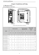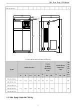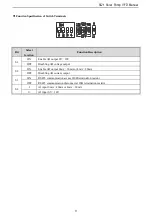
SI21 Solar Pump VFD Manual
8
●
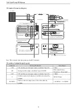
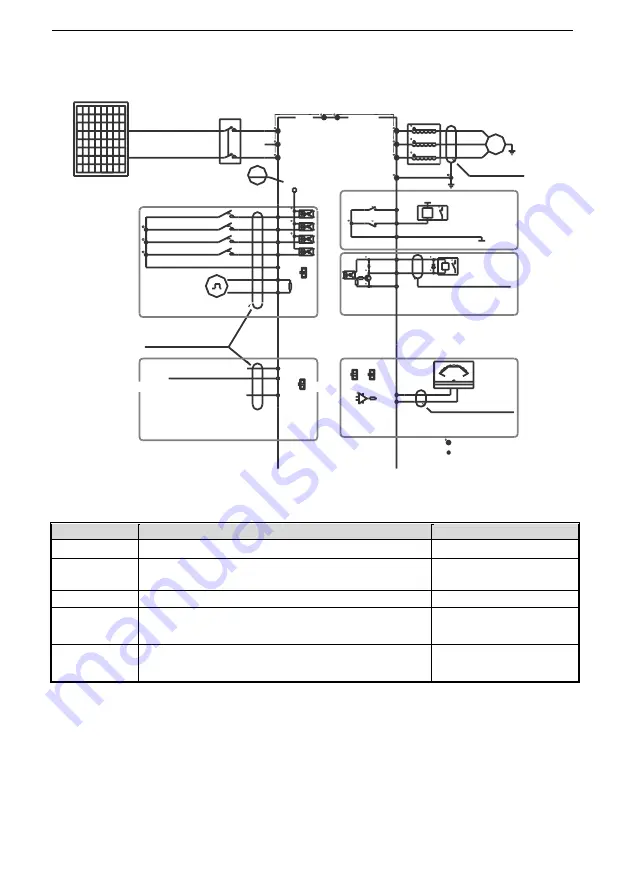
Standard Connection Diagram
Note2
Note:Function description in brackets is
factory default
A
n
a
lo
g
m
o
n
ito
rin
g
si
g
n
a
l o
u
tp
u
t
TA
TB
TC
+24V
Y
Shielded cable (the
end close to VFD
grounding)
_
mA
20
10
0
-
+
V
W
U
P
~
Shielded cable or armoured cable
(the end close to VFD grounding)
E
(The grounding resistance
is less than 10 ohms)
W
V
U
Output Rector
+10V
F
re
q
u
e
n
cy
co
n
tr
o
l in
p
u
t
GND
AI
Shielded cable (the end close to
VFD grounding)
M
u
lti
fu
n
ct
io
n
co
n
ta
ct
in
p
u
t
(Water full detection reset)
(Water full detection alarm)
(Reverse)
(Forward)
GND
X3
X4
X1
X2
PB
Solar pump VFD
S
T
R
GND
A0
Coil
COM
Pa
s
s
iv
e
c
o
n
ta
c
t
o
u
tp
u
t
AC220V
AC0V
Coil
MAX Output Of Contact:
3A/240VAC
5A/30VDC
1.MAX Output of +24V Port:DC24V/100mA
Note:When output type of AO port as
frequency and Voltage,
Maximum Output:2mA
2.Inner resistance of AI1/AI2 Port
:
100kΩ
1.MAX Output of +10V port :50mA
Note:
2.Max Output of Y Port :DC24V/50mA
Note:
represent control circuit terminals.
represent main circuit terminals;
Legend: 1.Symbol
Twisted pair shielded
cable (near the
inverter end
grounded)
P
+24V
Analog Voltage/Current quantity input
A+
B-
RS485 Differential
Communication
120Ω
O
p
e
n
co
lle
ct
o
r(
O
C
)
st
a
te
o
u
tp
u
t
2.Symbol
PV modules
DC breaker
S3
I
U
AI
S4
S1
U
S2
I
Note: When connect solar panel, please select R/T terminals.
●
Auxiliary Terminal Output Capacity
Terminal
Function Definition
Max Output
+10V
10V auxiliary power supply output, constitutes loop with
GND.
50mA
AO
Analog monitor output, constitutes loop with GND.
Max output 2mA as
frequency, voltage signal
+24V
24V auxiliary power supply output, constitutes loop with
COM.
100mA
Y
Collector open circuit output; can set the action-object by
program.
DC24V/50mA
TA/TB/TC
Passive connector output; can set the action-object by
program.
3A/240VAC 5A/30VDC


