background image

SI21 Solar Pump VFD Manual 


14 

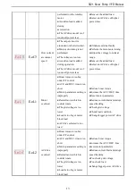
●AC drive selected is too 

load 


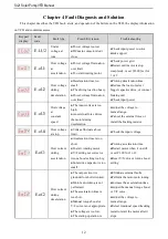
E.SC 

System 

abnormal   

●Deceleration is too short   
●Short circuit of solar drive 

output or phase output short 

circuit to ground   

● Module damage   
● EMC interface   

●Prolong acceleration time   
●To check peripheral equipment   
●Ask to support   
●Check the wiring layout, cable 

ground 


E.oH1 

VFD 

over-heat 

●Temperature is too high. 
●Air channel is blocked. 
●Fan connection parts is 

loose. 

●Fan is damaged. 
●Temperature detection 

circuit fault 

●Make the environment meet the 

requirement. 

●Clear the air channel. 
●Check and reconnect the wire 
●Change the same new fan.   
●Seek support from factory. 


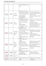
E.TE1 

Motor static 

detection 

fault 

●Detection overtime 
●Start static detection while 

motor is running. 

●Capacitance difference is 

too big between motor and 

VFD. 

●Motor parameter setting 

mistake. 

●Check motor connection wire. 
●Detect after motor stopping 

totally. 

●Change VFD model. 
●Reset parameter according to 

nameplate. 


E.TE2 

Motor 

rotation 

detection 

fault 

●Detect while motor is 

running. 

●Detect with load. 
●Detection overtime 
●Capacitance  difference  is 

too  big  between  motor  and 

VFD. 

●Motor parameter setting 

mistake. 

●Detect after motor stop totally. 
●Re-detect without load. 
●Check motor connection wire. 
●Change VFD model. 
●Reset parameter according to 

nameplate. 


E.EEP 

Memory 

fault 

●Electromagnetic disturb in 

memory period. 

●EEPROM damage. 

●Resume load and save. 
●Seek support from factory. 


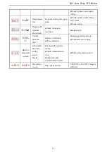
LiFE 

Reserved 


E.iLF 

Input phase 

loss   

●3-phase input power open 

phase. 

●Check 3-phase power supply 

and the phase. 

Summary of Contents for SI21

Page 1: ...s in Disposal 4 Chapter 2 Installation and Wiring 6 2 1 Dimension of VFD 6 2 2 Solar Pump Controller Wiring 6 Chapter 3 Keyboard layout and functions specification 10 Chapter 4 Fault Diagnosis and Sol...

Page 2: ......

Page 3: ...to carefully read the manual about safety installation operation and maintenance The safe operation depends on the proper processes of choosing models carrying installation operation and maintenance D...

Page 4: ...y VFD 5 Please don t connect the magnetic switch or magnetic contactor to the output circuit of frequency VFD When frequency VFD is in the operation with load magnetic switch or magnetic contactor can...

Page 5: ...ntain and repair the equipment with electric Otherwise it will cause electric shock 2 Before maintaining and repairing the frequency VFD please make sure the indicator lights of power supply have comp...

Page 6: ...between 480V and 560V while MPPT What means the solar panel open circuit voltage should be between 600V and 700V 1 4 Technical Specification Solar pump VFD power kW Pump Max solar power input kW Max...

Page 7: ...SI21 Solar Pump VFD Manual 5 3 Dispose method please dispose as industrial waste...

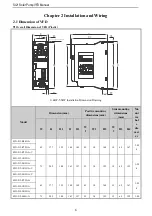
Page 8: ...nsions mm Side mounting dimensions mm Mo unt ing hol e dia met er W H H1 D D1 W 1 W2 H2 W 3 H3 H4 SI21 D3 R04G A 65 177 155 148 142 45 10 168 19 6 5 167 3 M 4 SI21 D3 R75G A SI21 D3 R75G A V C SI21 D3...

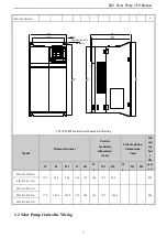
Page 9: ...awing Model Dimension mm Positive mounting dimensions mm Side mounting dimensions mm Mo unt ing hol e dia met er W H H1 D D1 W 1 W2 H2 W 3 H3 H4 SI21 D5 7R5G A 130 320 286 161 158 105 12 5 302 M5 SI21...

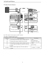
Page 10: ...ximum Output 2mA 2 Inner resistance of AI1 AI2 Port 100k 1 MAX Output of 10V port 50mA Note 2 Max Output of Y Port DC24V 50mA Note represent control circuit terminals represent main circuit terminals...

Page 11: ...n S1 ON Enable AO output 0V 10V OFF Disabling AO voltage output S2 ON Enable AO output 0mA 20mA or 4mA 20mA OFF Disabling AO current output S3 ON RS485 communication access 120 termination resistor OF...

Page 12: ...irm the modified value Shift function long press this button 1 second to move the operation bit long press is not loose then cyclic shift Up Down The up key increases the operation value and the down...

Page 13: ...n Indicates the frequency unit A Light on Represents current unit V Light on Represents voltage unit RPM Light on Express unit of speed Flash Light on Indicates the percentage unit Status Indicator RU...

Page 14: ...e input voltage is too high An external force drives the motor during deceleration Adjust the voltage to normal range Cancel the external force or install the braking resistor E oU4 Over voltage at st...

Page 15: ...is too big under VF control ACC and DEC time is too short Motor parameters setting is improperly Restart motor which in counter rotate The grid voltage is too lower Load is too big or motor block load...

Page 16: ...fault Detection overtime Start static detection while motor is running Capacitance difference is too big between motor and VFD Motor parameter setting mistake Check motor connection wire Detect after...

Page 17: ...and insulation Output earth E HA L Current detection fault Detect circuit fault Phase imbalance Seek support from factory Check motor and wiring Rs485co mmunicat ion fault Unsuitable baud rate settin...

Page 18: ...eyboard 22 Download parameters to the VFD 0 0 9999 F00 05 0x0005 User password V F SVC Used to set the user password 0 0 65355 Basic parameters Parameter address Function Description Range of settings...

Page 19: ...can set 50 00Hz upper limit frequency 600 00Hz F01 12 0x010C Upper limit frequency digital setting V F SVC The upper line frequency is given when F01 11 is set to 0 0 00Hz 0 00Hz upper limit frequenc...

Page 20: ...SI21 Solar Pump VFD Manual 18 F01 40 0x0128 Carrier frequency V F SVC Used to set the switching frequency of the VFD IGBT 4 0kHz 1 0kHz 16 0kHz...

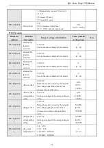
Page 21: ...the rated speed of the motor Model setting 0rpm 65000rpm F02 05 0x0205 Motor rated voltage V F SVC Set the rated voltage of the motor Model setting 0V 1500V F02 06 0x0206 Motor rated current V F SVC...

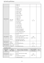
Page 22: ...time 2 0 100s 0 000s 6 000s F03 10 0x030 A Current loop D axis proportional gain SVC Set the current loop D axis proportional gain 1 000 0 001 4 000 F03 11 0x030B Current loop D axis integral gain SV...

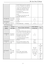
Page 23: ...al X for details 4 0 63 F05 03 0x0503 Terminal X4 function selection V F SVC See the function of terminal X for details 8 0 63 F05 50 0x0532 AI lower limit V F SVC Define the signal received by the te...

Page 24: ...nal vY1 0 0 19 F06 20 0x0614 Output terminal polarity selection V F SVC 0 Positive polarity 1 Negative polarity LED 0 digit Y terminal LED 00 digit Relay output terminal 1 LED 000 digit Reserved LED 0...

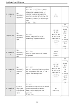
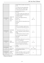
Page 25: ...and definition Factory default setting range Notes F10 00 0x0A0 0 Overcurrent suppression V F SVC The automatic limiting output current does not exceed the set overcurrent suppression point to prevent...

Page 26: ...oltag epoint 820V 750 840 S2 overvoltag epoint 400V 360 410 F10 18 0x0A1 2 Bus undervoltage suppression gain V F SVC Set the response effect of undervoltage suppression 100 0 0 0 500 0 F10 19 0x0A1 3...

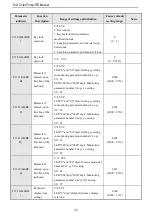
Page 27: ...ns after the VFD is powered on 1 After the shutdown the fan operation is related to temperature and the operation is running 2 After the shutdown the fan stops after F10 24 and the operation is relate...

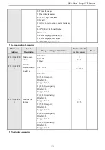
Page 28: ...11 12 0x0B0 C Parameter 2 showed up on first line of the keyboard V F SVC LED 0 and 00 digit Setting yy setting in monitoring parameter number Cxx yy 00 63 LED 000 and 0000 digit Monitoring parameter...

Page 29: ...of settings and definition Factory default setting range Notes F12 00 0x0C00 Master slave choice V F SVC 0 Slave 1 Host 0 0 1 F12 01 0x0C01 Modbus communicatio n address V F SVC 1 1 247 F12 03 0x0C03...

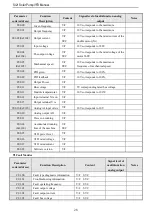
Page 30: ...VC C00 11 0x210B Bus voltage V F SVC 5V corresponding rated bus voltage C00 12 0x210C Module temperature 1 V F SVC 10V corresponds to 100 C00 14 0x210E Input terminal X is on V F SVC C00 15 0x210F Out...

Page 31: ...Forward prohibition 12 Frequency increment decrement clear UP DW clear 33 Acceleration deceleration time selection terminal 2 54 Reverse prohibition 13 Channel A switches to channel B 34 Suspension a...

Page 32: ...is ready for operation 22 Counter reaches maximum 36 Frequency detection 2 9 Output frequency level detection 1 FDT1 23 Counter reaches the set value 37 Frequency speed is consistent 2 10 Output freq...

Page 33: ...Motor 1 Single phase Motor 0002 F21 01 0x5501 Running control mode 0 Stop 1 Running 2 Sleep 3 Low speed protection 4 Dry run protection 5 Over current protection 6 Minimum power protection 7 Water fu...

Page 34: ...ow speed protection restore working time 0 0s 3000 0s 10 0s F21 17 0x5511 Dry run protection detect current 0 0A 999 9A 0 0A F21 18 0x5512 Dry run protection detect time 0 0s 3000 0s 10 0s F21 19 0x55...

Page 35: ...er curve point 0 0 00kW 99 99kW 0 50kW F21 33 0x5521 Power curve point 1 0 00kW 99 99kW 1 00kW F21 34 0x5522 Power curve point 2 0 00kW 99 99kW 1 50kW F21 35 0x5523 Power curve point 3 0 00kW 99 99kW...

Page 36: ...0x5532 Reserved F21 51 0x5533 Reserved F21 52 0x5534 Reserved F21 53 0x5535 Functional selection LED0 Inermittent Operation Storage 0 None 1 Storaged LED00 Stop Mode When Alarm 0 Slow down 1 Free stop...

Page 37: ...ower 0 01kW Read only C04 11 0x250B DC bus voltage 0 1V Read only C04 12 0x250C Module temperature 1 0 1 Read only C04 13 0x250D Status of MPPT Read only C04 14 0x250E Solar Panel Operation Point 0 1...

Page 38: ...DC current is incorrectly displayed A Adjust F21 30 F21 31 for calibration d Q Well lit conditions frequency severe beating during operation A Reasonably adjust F21 06 value the adjustment is recommen...

Page 39: ...e photovoltaic pump for some reason the output frequency is lower than F21 14 low frequency detection frequency and after F21 15 under frequency detection time time enters into the standby protection...

Page 40: ...Alarm Recovery Mode 0 automatic recovery 1 manual recovery This option is for low frequency protection dry protection over current protection minimum power function you can select the alarm restorati...

Reviews: