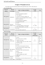
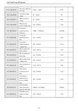
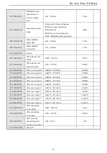
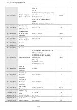
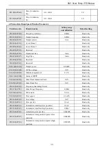

SI21 Solar Pump VFD Manual
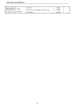
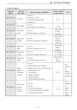
30
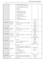
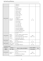
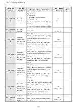
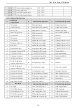
5
Fault trip alarm 2 (no
alarm during fault
self-recovery)
19
PID feedback sensor
disconnection
33
Frequency (speed) is
consistent 1
6
External downtime
20
Meter length arrives
34
Any frequency (speed) is
consistent 1
7
VFD is under-voltage
21
Timer time is up
35
Frequency detection 1
8
The VFD is ready for
operation
22
Counter reaches maximum
36
Frequency detection 2
9
Output frequency level
detection 1 (FDT1)
23
Counter reaches the set value
37
Frequency (speed) is
consistent 2
10
Output frequency level
detection 2 (FDT2)
24
Energy consumption braking
38
Any frequency (speed) is
consistent 2
11
Arrived at a given
frequency
25
PG feedback disconnection
39
Solar pump alarm output
12
Zero speed operation
26
Emergency stop
40
Reserved
13
Upper limit frequency is
reached
27
Overload pre-alarm output 1
41
Reserved


