4
PARTS AND CONTROLS
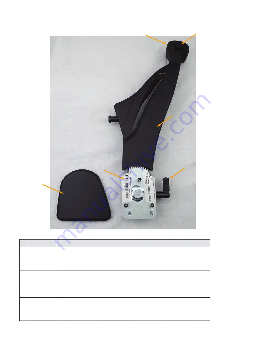
The operator components of an installed hand control are shown in Figure 2 and described in the
following table.
FIGURE 2: Parts & Controls
Description
No Name:
Pull this handle to work the accelerator pedal. See “Accelerator and Slowing
Down” on page 7.
1 Accelerator
Handle
Use this button to lock the brake. See “Locking the Brake” on page 8.
2 Brake
Button
During maintenance or repair only. The cover opens to reveal the connec-
tions made between the hand control and the rods that operate the vehicles
3 Contoured
Cover
Use this lever to disengage the controls and fold the hand control out of the
way. See “Disengaging the Hand Control” on page 8 when possible.
4 Control
Release
Lever
This cover is applied to the side of the brake gear box (item 6, below).
5 Lateral
Cover
Securely fastens the hand control to the inside of your vehicle.
6 Brake Gear
Box
2
1
4
6
3
5


