background image

3.1 Installation of Camera and Lens 

Carefully  read  the  instruction  manual  before  installation  to  learn  whether  the  CCD 

specifications  and  interface  forms  of  the lens  and  camera  are  consistent;  the  1/3 or  1/2  inch 

lens can be installed in the 1/3 inch CCD camera, and only the 1/2 inch lens can be installed 

in the 1/2 inch CCD camera, otherwise, vignette may be generated on the picture edge. 

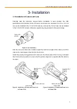
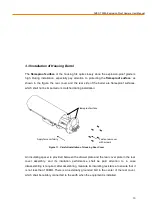
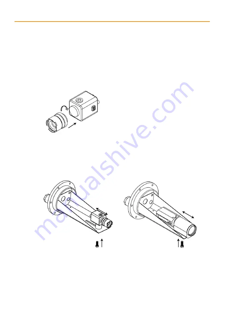
Figure 4. Lens Installation


After the lens and camera are installed, adjust the back focal length of the camera, and then 

observe the clear degree of test card on the monitor. 

Install the properly debugged lens and camera on the drawer plate of the housing, and adjust 

their front and rear positions to ensure that the picture edge has no vignette after the barrel is 

mounted. 

Figure 5. Installation of Camera and Prime Lens 

    Figure 6. Installation of Camera and Zoom Lens 

on Drawer Plate 

  on Drawer Plate


Tighten after 
insertion 

SVEX

-T500A

SVEX

-T500A

Adjust the front 
and rear 
positions 

Fasten with screw 

Fasten with screw 

Adjust the front 
and rear 
positions 

SVEX

-T500A Explosion Proof Camera User Manual. 

3- Installation

8

Summary of Contents for SVEX-T500A

Page 1: ...Explosion Proof User Manual SVEX T500A ...

Page 2: ...rwise it may cause faults 5 During maintenance of the equipment pay attention to the protection of flameproof surface avoid metal chips or other foreign matters from entering the equipment 6 Do not attempt to disassemble or modify the equipment 2 Environment Protection Our products may contain parts which pollute the environment such as circuit board electronic components plastic products and lubr...

Page 3: ...allation of Housing Barrel 10 3 4 Installation of Housing onto Electric Pan tilt 11 3 5 Installation of Housing onto Fixed Support 11 3 6 Installation Precautions 12 4 Description of Explosion proof Structure 13 5 Troubleshooting 13 6 Transportation and Storage 14 7 Installation Accessories 14 8 Quality Assurance 15 9 Declaration 15 Appendix I Lens Adjustment 15 Appendix II Use of Desiccant 16 App...

Page 4: ...ment dust ignition protection by enclosure t SVEX T500 series explosion proof camera has the enclosure of all stainless steel structure with the level of protection up to IP66 and can be widely used in the fields of petroleum chemical industry wharf port mine aerospace aviation military industry and grain processing etc SVEX T500 series explosion proof camera has 4 specifications including long ty...

Page 5: ...eater Power consumption Electrical connection Explosion proof camera with wiper long type 220VAC 110VAC 24VAC 50 60Hz 24V is a special type please specify when ordering 10 2A 12VDC provided by external equipment Started at the temperature below 10º C 5 º C 30W 2 core cable for power supply 4 core cable for lens control Video cable for video signal output Blank with wiper 1 without wiper A with wip...

Page 6: ... holes Thread size of outlet holes Installation mode 2 6 Ambient Condition Atmospheric pressure 80 110KPa Ambient temperature 40º C 60º C Relative humidity 95 RH 25º C SVEX T500A Explosion Proof Camera User Manual Stainless steel 304 or 316L IP66 657 L x 198 H x 212 W mm PP 15mm thick Φ80mm 16Kg 18Kg 3 G 3 4 or M25 1 5 Electric pan tilt semi fixed pan tilt fixed support ...

Page 7: ...oof All weather Camera Housing 2 8 Installation Dimension Figure 3 Fixing Holes at the Bottom of Housing SVEX T500A Explosion Proof Camera User Manual 2 7 Product Dimension Figure 1 Outside Dimension of SVEX T500A Explosion proof All weather Camera Housing ...

Page 8: ...alled adjust the back focal length of the camera and then observe the clear degree of test card on the monitor Install the properly debugged lens and camera on the drawer plate of the housing and adjust their front and rear positions to ensure that the picture edge has no vignette after the barrel is mounted Figure 5 Installation of Camera and Prime Lens Figure 6 Installation of Camera and Zoom Le...

Page 9: ...to use spare parts in the packaging box Figure 7 b As shown in Figure 8 first tighten the thread joint and then tighten the explosion proof Explosive proof seal joint Flat gasket Gasket Nut seat Rubber seal ring Outgoing cable Rubber gasket HPS89 01 epoxy resion Hold down nut Bakelite gasket A B type cable gland packing filled inside Explosion proof flexible tube Thread joint Rubber ring Gasket Ou...

Page 10: ...nstallation of Housing Rear Cover An insulating spacer is provided between the drawer plate and the rear cover plate in the rear cover assembly and its insulation performance shall be paid attention to in case disassembling is required after assembling measure its insulating resistance to ensure that it is not less than 100MΩ There is an externally grounded bolt in the center of the rear cover whi...

Page 11: ... jumper from No 2 terminal to No 3 terminal white 3 S N 3 consists of 2 line groups One group is for the wiper limit switch white the other group is the jumper from No 2 terminal to No 3 terminal white 4 S N 4 consists of 3 line groups One group is for the capacitor red one group is for the motor 0 14mm 2 red and the other group is for the wiper limit switch brown 3 4 Installation of Housing onto ...

Page 12: ... ring select the minimum cable OD as per the mark on the end face of the rubber seal ring and guarantee that the gaps between the rubber seal ring and the cable as well as the rubber seal ring and the lead in device meet the explosion proof requirement after the hold down nut is tightened Set the nameplate and the warning sign No Opening with Power in an obvious position on the surface of the prod...

Page 13: ...e mixture outside the equipment if sparks are generated in the equipment moreover the explosion proof performance of the equipment is guaranteed from the following aspects enclosure strength gap between components and highest surface temperature limitation of enclosure The explosion proof enclosure after finish machining must be able to withstand the hydraulic test pressure specified in GB3836 2 2...

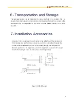
Page 14: ...in the outlet hole of the camera and 10mm blocking core and hold down nut are mounted in the hole without threaded line Provide one 8mm rubber seal ring one 12mm rubber seal ring and one portion of desiccant provide one 1 4 copper screw one 6mm copper screw and one 12mm copper screw for the housing Other accessories to be ordered separately Figure 16 SVEX M1 Support SVEX M1 Side View SVEX M1 Top V...

Page 15: ... or Act of God If there are additional agreements between Veilux and buyer then agreements shall be strictly done 9 Company Commitment Veilux owns the final design changing and final specification rights and no responsibility to inform user This manual book belongs to Veilux rights without permits or any book inform any company or private copy of whole or part of the book shall be prohibited Appen...

Page 16: ... ring and mean WIDE and TELE adjusting towards the W direction increases the view angle of the lens to the maximum so W means wide angle adjusting towards the T direction decreases the view angle and thus farther views can be seen and N are marked on the focusing ring and mean Infinite and NEAR respectively focusing is adjusted as per the distance i e object distance of the observed view till the ...

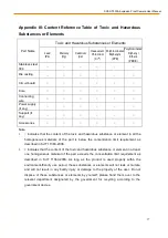
Page 17: ...homogeneous materials of the part is below the concentration limit requirement as described in SJ T 11363 2006 2 indicates that the content of the toxic and hazardous substance or element in at least one homogeneous material of the part exceeds the concentration limit requirement as described in SJ T 11363 2006 As long as the product is used properly within the environment friendly use period thes...

Reviews: