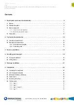
Description and main characteristics
General instructions
9
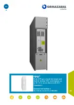
cpg.1
Fully SF6 gas insulated single and double busbar GIS switchgears up to 36 kV in accordance
with IEC Standards
IG-137-EN version 03; 23/06/2016
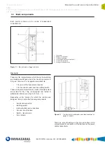
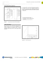
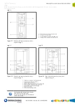
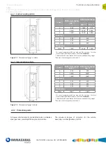
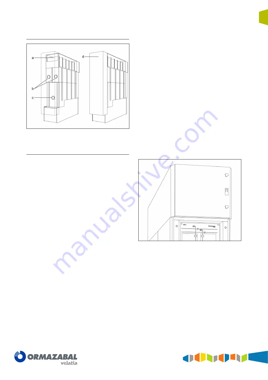
Gas pressure relief duct (optional)
Figure 1.4
Internal arc gas pressure relief duct (optional)
This component is used to direct the gases produced by
an internal arc in any of the compartments towards the
top of the cubicle: Disconnector compartment and circuit
breaker compartment, top busbar compartment and cable
compartment.
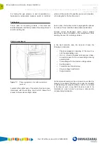
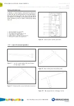
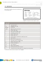
Control compartment
Placed at the top of the cubicle and separate from the
medium voltage area, this is ready for installation of the
metering equipment and protection relays. It contains
the whole terminal block with the control signals already
identified.
Figure 1.5
Control compartment
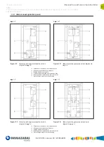
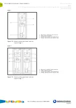
a. Gas vent from busbar compartment
b. Gas vent from disconnector compartments
c. Gas vent from circuit breaker and earthing switch
compartment
d. Internal arc gas directional duct (optional)
Summary of Contents for Ormazabal cpg.1 Series
Page 67: ......


