background image

Description and main characteristics

General Instructions

ormaSET-M

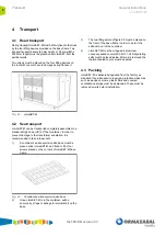
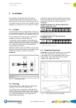
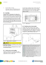
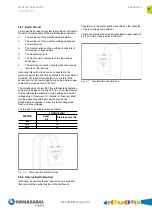
IG-199-EN version 03

1

Description and main characteristics

Ormazabal

's


ormaSET-M


is a kiosk-type Metallic 

Prefabricated Transformer Substation, installed on surface


and externally operated, with reduced dimensions, 
standard-built, factory tested and supplied from the factory 
as a unit.

ormaSET-M Transformer Substation complies with the 
requirements established in standard IEC 62271-202.

ormaSET-M is designed for end-user networks with rated 
voltages U

r

 up to 36 kV and a rated power of 1000 kVA.

Ormazabal

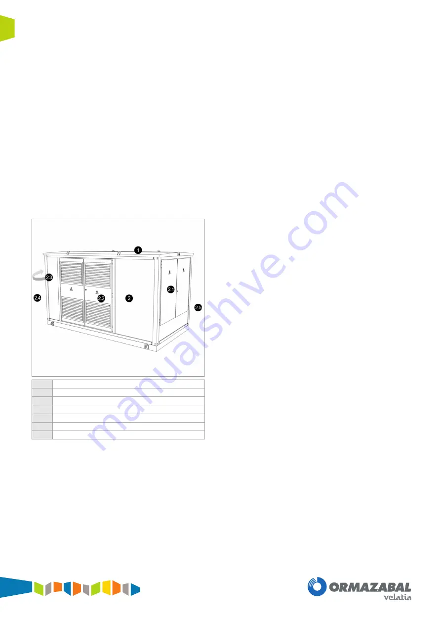
's ormaSET-M Transformer Substation is made 

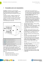
up of the following main components:

Fig. 1.1:

Main Components of ormaSET-M

It is characterised by the incorporation of medium voltage 
(MV) equipment for public distribution networks up to 
36 kV. It has independent accesses for the medium voltage 
switchgear compartment, for the transformer compartment 
and for the low voltage switchboard compartment.

Made up of:

Metal prefabricated enclosure.

Removable roof dimensions 4046 x 2275 mm.

Access doors to the electrical switchgear:

Double access doors and dimensions of 
997 x 1400 mm in the medium voltage area and 
low voltage board area. Folding doors at 90º and 
180° on the outside wall, hinged, with a two fixing 
point and a fastening rod to hold them open 
preventing untimely closures. 

Snow panel below medium voltage and low 
voltage doors, dimensions 1997 x 486 mm.

Access doors to the Transformer: Two accesses 
to the transformer, one on either side, made up of 
double doors of 963 x 1890 mm, folding at 90º 
and 180° on the outside wall, hinged, with a two 
fixing point and a fastening rod to hold them open 
preventing untimely closures.

Air intake and exhaust grille for natural ventilation, 
fitted with a grille of 6 x 6 mm.

Optionally, a closing system for the medium voltage 
input cables in the lower part of the enclosure. Up to 
3 input cables for 3 x 1 x 240 mm

2

 XLPE 18/

30 kV H16. Maximum single core cable diameter 
90 mm.

Optionally, a closing system for the low voltage 
input cables in the lower part of the enclosure. Up to 
8 input cables for 4 x 1 x 240 mm

2

 XZ1 0.6/1 kV. 

Maximum single core cable diameter 90 mm.

Base frame manufactured with laminated profiles 
UPE 140

Optionally, an oil collection pit made of galvanised 
sheet metal, with a capacity of 600 litres.

Optionally protective earth disconnection box and 
service earth disconnection box can be supplied, 
located in the low voltage compartment on the left 
and right of the low voltage switchgear.

Earth circuit, copper conductor cross section 
50 mm

2

.

Document holder for general instructions relating to 
the transformer substation.

Lighting in the medium voltage, low voltage and 
transformer compartments supplied.

Optionally, emergency lighting of 50 Lm 1h NM, 
IP42, IK04 1 x 6W, class II, 230 V 50/60 Hz. 
According to standard IEC 60598-2-22.

Physical separation between the medium voltage 
compartment, power transformer and low voltage 
compartment.

1

Roof of prefabricated substation

2

Enclosure of prefabricated substation

   2.1

Medium voltage switchgear door

   2.2

Power distribution transformer door

   2.3

Low voltage switchboard door

   2.4

Medium voltage cable inter-connection

   2.5

Low voltage cable inter-connection

Summary of Contents for Ormazabal ormaSET-M

Page 1: ...ormaSET M General Instructions IG 199 EN version 03 6 11 2013 Prefabricated metallic transformer substation ...

Page 2: ...re applicable to the situation according to current legislation The above must be carefully observed as the correct and safe operation of this equipment depends not only on its design but also on general circumstances which are in general beyond the control and responsibility of the manufacturer More specifically The equipment must be handled and transported appropriately from the factory to the p...

Page 3: ... 2 Sea transport 8 4 3 Packing 8 5 Installation 9 5 1 Location 9 5 2 Planning 9 5 3 Preparing the ground 9 5 4 Handling 10 5 5 Cable access and sealing 10 5 6 Earthing circuit connection 10 5 6 1 Earth Circuit 11 5 6 2 Service Earth Neutral 11 6 Replacement electrical equipment 12 6 1 Medium voltaje switchgears and low voltage switchboard substitution 12 6 2 Transformer substitution 12 7 Operation...

Page 4: ...made up of double doors of 963 x 1890 mm folding at 90º and 180 on the outside wall hinged with a two fixing point and a fastening rod to hold them open preventing untimely closures Air intake and exhaust grille for natural ventilation fitted with a grille of 6 x 6 mm Optionally a closing system for the medium voltage input cables in the lower part of the enclosure Up to 3 input cables for 3 x 1 x...

Page 5: ...271 200 The following models can be installed CGMCOSMOS 12 and 24 kV 400 630 A CGM 3 36 kV 400 630 A MV LV distribution transformer according to IEC 60076 1 oil filled and hermetically sealed fully equipped with medium voltage solid insulated bushings up to 1000 kVA 36 kV Low voltage LV board according to IEC 61439 1 with up to 8 outputs for NH 2 size fuses Medium voltage inter connection HEPRZ1 3...

Page 6: ...ve humidity value measured in a 24 hour period must not exceed 95 Vapour Pressure average 1 month 22 mbar Altitude The altitude of the place of installation must not exceed 1000 m For working conditions that differ from those given or that are not mentioned in these instructions it is necessary to define what they are and to study how they affect the design In the event of special conditions of us...

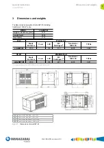
Page 7: ...ormaSET M MODEL ormaSET M Height on level zero mm 2301 Length mm 3936 Depth mm 2126 24 kV Weights kg Empty Enclosure Cover LVB MV Switchgear 1 Transformer 1000 kVA TOTAL ormaSET M 2100 150 310 2400 4960 36 kV Weights kg Empty Enclosure Cover LVB MV Switchgear 1 Transformer 1000 kVA TOTAL ormaSET M 2100 150 487 2500 5237 A Transformer side gap 1900 mm B Transformer side gap 1940 mm C Transformer to...

Page 8: ...ount 1 A container sea transport wooden base must be placed under ormaSET M and fixed to it by four screws placed on the corners of ormaSET M base frame Fig 4 2 Container sea transport wooden base 2 Once ormaSET M is in the container will be secured by straps or airbags to immobilize it on the base 3 The two lifting points of figure 5 3 must be placed on the front of the base frame in order to per...

Page 9: ...n the location sketch or drawing mark out the spaces available for the crane and the transport truck The existence of any circumstance or object that could impede or obstruct the smooth operation of the installation must be indicated posts cables ditches walls pipelines etc marking their positions on the drawing with the corresponding measurements Attached is a table of values for the different cr...

Page 10: ... area The transformer substation has three cables inputs in the medium voltage compartment each one up to a single cable diameter of 90 mm In the low voltage compartment there are 8 outgoings each one up to a single cable diameter of 90 mm Fig 5 4 Cable access 5 6 Earthing circuit connection ormaSET M has a main earthing conductor system provided to connect to the earth all metallic parts of the p...

Page 11: ...w voltage board using a bare copper cable with a cross section of 50 mm2 The metallic parts of ormaSET M prefabricated substation enclosure is designed to carry 30 A d c from themselves to the prefabricated substation main earthing point with a voltage drop of maximum 3 V Installer or final user shall provide adequate earthing measures around the prefabricated substation in order to prevent danger...

Page 12: ...nstructions 6 In order to recommission ormaSET M transformer substation the above procedures must be carried out in inverse order 6 2 Transformer substitution To replace the transformer follow the procedure below 1 Remove power supply in the medium voltage and low voltage incomings to ormaSET M transformer substation Follow the electric utility company procedure and the local electrical safety reg...

Page 13: ...ns ormaSET M IG 199 EN version 03 7 Operation Clean the substation of all dirt from the storage transport and installation If the paint has been damaged it must be repaired according to Ormazabal instructions Please contact Ormazabal ...

Page 14: ...lly maintained according to local regulations When performing maintenance local electric safety regulations must be taken into account Maintenance actions generally include cleaning and inspection of the equipment Maintenance procedures of the equipment must be fulfilled according to the general instructions of the manufacturer ...

Page 15: ......

Page 16: ...Subject to changes without prior notice For more information contact Ormazabal Ormazabal Distribución Secundaria IGORRE Spain www ormazabal com ...

Reviews: