- 4 -
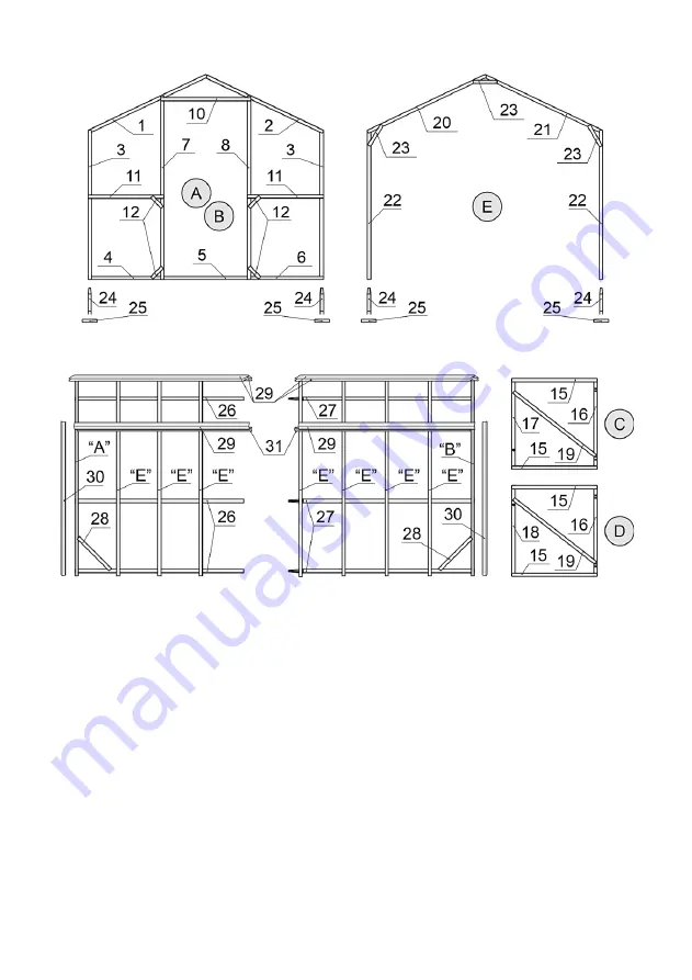
2. ASSEMBLY DIAGRAM
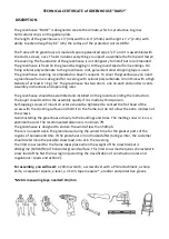
“DAISY” PRODUCT
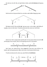
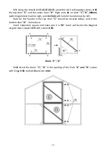
Fig.1 Ends
“
A
”,“
B
”
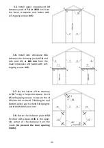
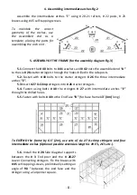
Fig.2 Intermediate arch "E"
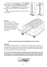
Fig.3 Assembling frame (side view)
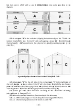
Fig.4 Doors "C", "D"
3.
Assembling Ends "A" and "B" (identically the same). Fig.1
Attention! Places of fastening parts are indented and circled with a marker.
Polycarbonate mounting places are only indented.
To maintain the correct geometry, assembly must be done on a level and flat
surface.
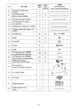
Before reassembling, sort and lay out the end caps, doors and intermediate
arches parts according to the diagram and the parts list.
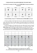
Punching holes for fixing polycarbonate on the details of the ends and doors
should be located on one side.
For convenience and acceleration of assembly, fastening of parts with self-
tapping screws can be done on one side of the assembly element, then carefully turn
the structure over and fix the screws on the other side.


