background image

- 22 -

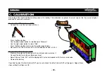
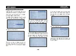
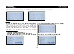
The display will look more or less like below:

Now, touch the red alligator clip with your finger.  Your body acts like an antenne and touching the clip will induce ‘noise’ to the input of the scope.

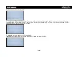
The unit will trigger and the display will show a single screen of the noise you’ve injected trough your finger.  Next, the scope will switch to ‘HOLD’-

mode. Now you have plenty of time to study the screen.

To capture the next event, press the ‘HOLD’-button briefly.

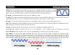
Triggering is re-armed and when you touch the red alligator clip again, the screen will refresh:

Let’s measure

Summary of Contents for EDU08

Page 1: ...w velleman proj ects eu Discover the worlD of electronics fr Kit d oscilloscope ducatif afficheur lcd nl educatieve lcd oscilloscoopKit de oszillosKop lernpaKet lcd display es Kit educativo con oscill...

Page 2: ...Velleman N V Legen Heirweg 33 9890 Gavere Belgi...

Page 3: ...Forum Forum Need support Check our Velleman Projects Forum Subscribe to our newsletter visit www vellemanprojects eu...

Page 4: ...ments on voltages higher than 30Vpp Maximum input voltage 30Vpeak AC DC Maximum sample rate 1MS s for repetitive signals Measurements can be performed up to 100kHz Timebase range in 15 steps 10 s divi...

Page 5: ...ivers A basic range is fine For some projects a basic multi meter is required or might be handy 1 2 Assembly Hints Make sure the skill level matches your experience to avoid disappointments Follow the...

Page 6: ...6 DO NOT BLINDLY FOLLOW THE ORDER OF THE COMPONENTS ON THE TAPE ALWAYS CHECK THEIR VALUE WITH THE PARTS LIST...

Page 7: ...s on the component side R1 220 2 2 1 B R2 560 5 6 1 B R3 1K 1 0 2 B R4 1K1 1 1 0 1 1 R5 2K4 2 4 0 1 1 R6 10K 1 0 3 B 1 Vertical resistors Display PCB R Solderside 2 Ceramic Capacitors C1 1 F 105 C2 1...

Page 8: ...h the polarity C11 100nF 104 C12 100nF 104 C13 100nF 104 C14 100nF 104 C15 100nF 104 C16 100nF 104 c Watch the position of the notch IC1 16p IC2 8p IC3 28p SW1 on off L L1 100 H 1 0 1 B L L c RV1 5K G...

Page 9: ...1 0 3 B R22 10K 1 0 3 B R23 10K 1 0 3 B R24 11K 1 1 0 2 1 R25 15K 1 5 3 B R26 18K 1 8 3 B R27 20K 2 0 0 2 1 R28 22K 2 2 3 B R29 75K 7 5 0 2 1 Watch the polarity C22 10 F C23 10 F C24 10 F C25 100 F C2...

Page 10: ...s shown in the drawing 17 Mounting the test leads Tip Start with one cable and then do the other 18 Mounting the battery holder STEP 1 Stick one part of the included hook and loop strap hooks on one o...

Page 11: ...ace the opening on the cardboard STEP 2 Stick the other part of the hook and loop strap loops in the centre of the traced area on the cardboard cover and put the parts together Remember to place 4 AAA...

Page 12: ...ight arrow button to select Vdc Press the Menu button to return to the oscilloscope display Now adjust the Offset trimmer RV2 until the displayed value is 0 00V To adjust the Gain trimmer RV1 Measure...

Page 13: ...OFF slide switch Slide in the upper position to turn on unit Remark To stretch the life of your batteries the unit will turn off after approx 10 minutes if left idle Press any key to resume If you do...

Page 14: ...is safe 1 Vertical divisions There are 8 vertical divisions 2 Trigger level and trigger slope 3 Time division setting When displayed in reverse video automatic time division setting is active 4 Indic...

Page 15: ...correctly you should see a square wave displayed Do not connect the BLACK alligator clip The test pin provides a square wave output with a frequency of approximately 2kHz 2000Hz Note that the volts di...

Page 16: ...UTO Volt The unit automatically selects correct V div setting 0 1V div Full screen range 0 8V 0 2V div Full screen range 1 6V 0 5V div Full screen range 4V 1V div Full screen range 8V 2V div Full scre...

Page 17: ...play a value Vdc Display the level of the DC component of the signal Vac Display the level of the AC component of the signal Vac dc Display the level of the complete signal Vpk pk Display the peak to...

Page 18: ...sely at the number of vertical divisions the trace almost reaches the second division and the volts div setting is 5V div so the measured voltage is a little less than 2x5V or 10V How much is the exac...

Page 19: ...e DC component of the signal is blocked The scope only displays the AC part which is both positive and negative Let s measure the frequency and period of our waveform First we turn on the markers by p...

Page 20: ...anging the trigger level Now we can change the trigger level by pressing the UP or DOWN keys The slope symbol also indicates the trigger level If you move the trigger level to the the center posi tion...

Page 21: ...are reached and when it reaches the right hand side of the screen it will stop drawing and switch to HOLD mode Press the HOLD button again to re arm the trigger and wait for the next event to happen...

Page 22: ...ut of the scope The unit will trigger and the display will show a single screen of the noise you ve injected trough your finger Next the scope will switch to HOLD mode Now you have plenty of time to s...

Page 23: ...AN OSCILLOSCOPE WE ENCOURAGE YOU TO FURTHER ExPERIMENT AND DISCOVER ALL FEATURES OF YOUR OSCILLOSCOPE For more in depth info about oscilloscopes in general their features and their opera tion check ou...

Page 24: ...ost positive and most negative swing of the signal 2xVpeak for sinusoidal signals 3 4 8 7 6 AC coupling The oscilloscope only displays the AC component of a signal any DC level is ignored AC voltage A...

Page 25: ...d handle all the calculations and displaying in the digital domain Digital signals feature only two fixed levels usually 0V and 5V See also Analog Distortion Undesired alteration of a signal due to ex...

Page 26: ...0kS s in real time Signal Voltage applied to the input of the oscilloscope The subject of your measurement Sine wave Mathematical function that represents a smooth repetitive oscillation The waveform...

Page 27: ...27 PCB BASE PCB...

Page 28: ...28 PCB DISPLAY PCB...

Page 29: ...29 PCB DISPLAY PCB...

Page 30: ...30 Diagram...

Page 31: ...istor Example operate a red led 1 7V on a 9Vdc source Required led current for full brightness 5mA this can be found in the datasheet of the led LEDs in series Example 3 x red led 1 7V on 9V battery R...

Page 32: ...Modifications and typographical errors reserved HEDU08 2013 ED1 Velleman nv Legen Heirweg 33 9890 Gavere Belgi...

Reviews: