background image

Total solder points: 600 
Difficulty level:  

  beginner

 1

o

  2

o

  3

o

  4

o

  5

þ


advanced


MANUAL 

H8011P-ED1 


MONO VALVE POWER AMPLIFIER 
MODULE


K8011


⇒ 

Pure valve sound with EL34 valves 

⇒ 

Easy bias adjustment with LED indication 

⇒ 

High quality capacitors and components 

⇒ 

Standby function 

⇒ 

Soft start circuit for power transformer 

⇒ 

Single PCB ensures hassle-free assembly and wiring  

⇒ 

High quality toroid transformers 

⇒ 

Sensitivity adjustment for exact level matching of two mono amps 

⇒ 

A special chassis plate is also available, order code: CHP8011 


Specifications 


• 

90Wrms in 4 or 8

 (at rated mains voltage) 

• 

Bandwidth: 2Hz to 125KHz (-3dB/1W) 

• 

Harmonic distortion: 0.1% @ 1W/1KHz 

• 

Signal to noise ratio: 104dB (A weighted) 

• 

Input sensitivity: 1Vrms min. (adjustable) 

• 

Supply voltage: 100, 120, 230 or 245VAC 

• 

Stand by power consumption: 60W 

• 

Maximum power consumption: 230W 

• 

PCB dimensions: 245 x 320mm (9.65” x 12.6”) 

modifications reserved 

Summary of Contents for K8011

Page 1: ...ssembly and wiring High quality toroid transformers Sensitivity adjustment for exact level matching of two mono amps A special chassis plate is also available order code CHP8011 Specifications 90Wrms...

Page 2: ...d 2 3 Aranciato Laranja Naranjado Oranssi Orange Orange Orange Orange Orange Orange Oranje 3 4 Giallo Amarelo Amarillo Keltainen Gul Gul Gul Gelb Yellow Jaune Geel 4 5 Verde Verde Verde Vihre Gr n Gr...

Page 3: ...ormer Switch on delay to protect the output valves approx 1 minute Standby circuit Built in bias current indicator Switch on delay for the supply transformer 0 5s Power bandwidth 8 45kHz 3dB ref 50W F...

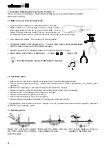
Page 4: ...for bending leads or to hold components in place Small blade and phillips screwdrivers A basic range is fine For this projects a basic multi meter is required 1 2 Assembly Hints Make sure the skill l...

Page 5: ...by putting the four large valve sockets in place This will allow us to rest the board on the bench without having the component leads touching the bench surface When the component leads are put in the...

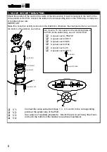
Page 6: ...n exactly as shown in the illustration otherwise the small piece of wire could touch the bottom of the cabinet see further 2 3 4 1 3 5 7 4 6 5 8 1 8 q V1 q V2 q V3 q V4 Also mount a 15 mm spacer on th...

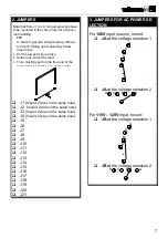
Page 7: ...0 q J21 3 JUMPERS FOR AC POWER SE LECTION For 100V input mains mount q JA at the voltage selection 1 D C B A q JA at the voltage selection 2 D C B A For 115V 120V input mount q JB at the voltage selec...

Page 8: ...on 1 D C B A q JD at the voltage selection 2 D C B A 4 DIODES Check the polarity D CATHODE q D1 1N4148 q D2 1N4148 q D3 1N4007 q D4 1N4148 q D5 1N4007 q D6 1N4148 q D7 1N4148 q D8 1N4148 q D9 1N4007 q...

Page 9: ...470K 4 7 4 B q R18 680 6 8 1 B q R19 3K9 3 9 2 B q R20 10K 1 0 3 B q R21 10K 1 0 3 B q R22 1K5 1 5 2 B q R23 1K2 1 2 2 B q R24 560 5 6 1 B q R25 100K 1 0 4 B q R26 220K 2 2 4 B q R27 100K 1 0 4 B q R...

Page 10: ...180 1 8 1 B q R69 180 1 8 1 B q R70 10 1 0 0 B q R71 10 1 0 0 B q R72 180 1 8 1 B 8 LEDs Check the polarity LD COLOR 2 5 CATHODE q LD1 5mm red 2 blinking q LD2 3mm bicolor power standby on indication...

Page 11: ...KETS Check the position of the notch IC 1 q IC1 18P 10 REED RELAY Check the position of the notch PIN 1 1 RY q RY1 VR05R121 11 DIP SWITCHES 1 SW Check that switch 1 corresponds to pin 1 q SW2 DS 4 12...

Page 12: ...very important SK q SK1 4 Ohm q SK2 GND q SK3 8 Ohm q SK4 BLUE q SK5 RED q SK6 YELLOW q SK7 GRAY q SK8 GRAY q SK9 GREEN q SK10 GREEN SK21 and SK22 will not be used 16 CINCH RCA CONNECTOR Mount it as...

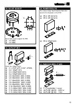
Page 13: ...0 q C2 100pF 101 q C3 330pF 400V 331 q C4 330pF 400V 331 q C5 68n 630V 683 0 068 q C6 68n 630V 683 0 068 q C7 68n 630V 683 0 068 q C8 68n 630V 683 0 068 q C9 68n 630V 683 0 068 q C10 68n 630V 683 0 06...

Page 14: ...7 q C15 100 F q C16 470 F q C17 470 F q C18 470 F q C19 470 F q C20 47 F 100V q C21 100 F 100V q C22 1000 F q C23 4700 F q C24 47 F 350V q C25 47 F 350V q C26 100 F q C27 1 F 23 TRANSFORMER TRAFO q TR...

Page 15: ...wn wire Twist them as shown in the illustration The polarity is not important For safety it is advisable to check with an ohmmeter that the two 6 3V terminals are not shorted when the wiring is comple...

Page 16: ...sis by means of the metal spacer located next to the RCA input A 470 Ohm resistor avoids hum loops Provide plenty of ventilation as tubes run very hot Use the provided mains inlet together with a suit...

Page 17: ..._________________________________ 17 FIG 3 Fasten the mains inlet with two suitable bolts and nuts M3 BOLT M3 NUT FIG 4 Fasten the PCB to the chassis with M3 bolts Mount the supply transformer the sma...

Page 18: ...___________________________________________________________________________________________ 18 M8 BOLT RUBBER WASHER TRANSFORMER RUBBER WASHER STEEL DISHED WASHER M8 NUT FIG 5 The output transformer t...

Page 19: ...r rating label and stick it onto the chassis or enclosure on a clearly visible location The transformers IMPORTANT Do not trim the wires of the transformers leave them at their original length If ther...

Page 20: ...wire with the connector marked RED SK5 Connect the blue wire with the connector marked BLUE SK4 Use female push on connectors and solder them to the wires for best results SOLDER FIG 8 Connect the rem...

Page 21: ...__________________________________________________________________________________________________________________________________________________________ 21...

Page 22: ...______________________________________________________________ 22 Function LED Use an appropriate length of the supplied multicore cable and make the connection between the two color LED and SK20 as s...

Page 23: ...y green indicating ON and a relay should click Now check the following voltages with a multimeter Measure about 6 3VAC between SK7 SK8 and SK9 SK10 Measure about 6 3VAC between pins 2 and 7 of the tub...

Page 24: ...ols V2 etc IMPORTANT This calibration determines the bias current trough the expensive output valves Therefore it requires your absolute attention Perform the calibration in the correct order No signa...

Page 25: ...ivity so two units put out exactly the same level which improves the stereo image Normally this trimmer should be set fully clockwise If necessary feed a mono signal to both amplifiers and trim both s...

Page 26: ...h the same value and power rating A continuous buzzing sound coming from the speakers or a crackling sound during bass peaks could be caused by oscillation of the amplifier In this case try raising th...

Page 27: ...__________________________________________________________________________________________________________________________________________________________ 27 DIAGRAMS...

Page 28: ...6 ORANGE BROWN BLACK J4 J5 J6 J9 J7 J8 J10 J12 J19 J20 J21 J11 R30 C9 C10 C7 C8 230V 120V 100V 0 D C B A VOLTAGE SELECTION1 A 100VAC B 120VAC C 230VAC D 245VAC RED ORANGE VIOLET D C B A SELECTION2 VOL...

Page 29: ...007 LD1 L 56BHD GREEN D24 1N4148 12VDC C18 470u R1 470 D18 1N4007 D17 1N4007 D20 1N4007 R23 1K2 RED R24 560 D21 1N4007 ON SW1 OFF STB C16 470u C15 100u R22 1K5 R2 220K V ZD1 3V9 C14 4u7 R5 220K D1 1N4...

Page 30: ...1 100K 300VDC R62 100K 1W 110VDC R11 3K9 R50 100K 5W V5 7 ECC81 R41 100K 5W C3 330p 400V V2 R63 47K 1W C5 68n 630V 2 6 1 C10 68n 630V 220VDC R27 100K C9 68n 630V R25 100K V BLACK GREEN VIOLET 0 4VDC B...

Reviews: