background image

AVM360                                                                                                                                      GB

4

Test

Range Position

Scale to read

Multiplier

DC 0.1V

B

10

0.01

0.5V

B

50

x 0.01

2.5V

B

250

x 0.01

DC Volt

10V

B

10

x 1

50V

B

50

x 1

250V

B

250

x 1

1000V

B

10

x 100

AC

10V

C

10

x 1

AC

50V

B

50

x 1

Volt

250V

B

250

x 1

1000V

B

10

x 100

DC

50 µA

B

50

x 1

DC

2.5 mA

B

250

x 0.01

Current

25 mA

B

250

x 0.1

0.25 A

B

250

x 0.001

x 1

A

x 1

x 10

A

x 10

Resistance

x 100

A

x 100

x 1 K

A

x 1000

x 10 K

A

x 10000

AC

10 V

G

x 1

Decibel

50 V

G

x 1 + 14 dB

250 V

G

x 1 + 28 dB
x 1

Iceo

x 1

E

(for big TR)

x 10

E

x1
(for small TR)

hFE

x 10

D

x1

x 1K

E

µA x 10

F

x  1

x 100

E

µA x 100

Diode

F

x 1

x 10

E

mA x 1

F

x  1

x 1

E

mA x 10

F

x  1

Summary of Contents for AVM360

Page 1: ...AVM360 Analog multimeter OPERATION MANUAL GEBRUIKERSHANDLEIDING MANUEL D UTILISATEUR ...

Page 2: ...n possible However safe operation depends on you the operator Make sure you follow these simple safety rules l Never apply a voltage to the multimeter that exceeds the limits given in the specifications Never apply more than 1000V DC or 1000V rms AC between an input jack and ground l Use extreme caution when working with voltages above 60V DC or 30 V AC rms l Always discharge filter capacitors in ...

Page 3: ... cause the multimeter to work improperly l Use only fresh batteries of the required size and type Always remove old or weak batteries If you do not plan to use the multimeter for a month or more remove the batteries This protects the multimeter from possible leakage l Disconnect the test probes before opening the multimeter l Replace blown fuse only with same size and type F 1 5A 250V l If any fau...

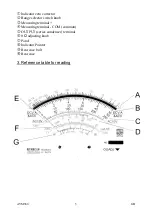
Page 4: ...rrector ô Range selector switch knob í Measuring terminal Measuring terminal COM common û OUTPUT series condenser terminal ø 0 Ω adjusting knob ù Panel î Indicator Pointer ü Rear case bolt ê Rear case 3 Reference table for reading ...

Page 5: ...olt 250V B 250 x 1 1000V B 10 x 100 DC 50 µA B 50 x 1 DC 2 5 mA B 250 x 0 01 Current 25 mA B 250 x 0 1 0 25 A B 250 x 0 001 x 1 A x 1 x 10 A x 10 Resistance x 100 A x 100 x 1 K A x 1000 x 10 K A x 10000 AC 10 V G x 1 Decibel 50 V G x 1 14 dB 250 V G x 1 28 dB x 1 Iceo x 1 E for big TR x 10 E x1 for small TR hFE x 10 D x1 x 1K E µA x 10 F x 1 x 100 E µA x 100 Diode F x 1 x 10 E mA x 1 F x 1 x 1 E m...

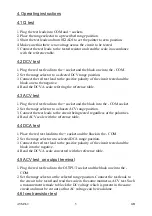
Page 6: ...et and the black into the COM socket 2 Set the range selector to a chosen ACV range position 3 Connect the test leads to the circuit being tested regardless of the polarities 4 Read ACV scale with the reference table 4 4 DCA test 1 Place the red test lead into the socket and the black in the COM 2 Set the range selector at a selected DCA range position 3 Connect the red test lead to the positive p...

Page 7: ...minal with the EMITTER E of the transistor For PNP transistor reverse the NPN transistor connection 5 Read Iceo range If the pointer is within the LEAK zone or the pointer moves up near the full scale the tested transistor is not good Otherwise it is a good transistor 4 7 hFE DC amplification transistor test 1 Set the range selector to x 10 2 Adjust 0Ω ADJ to adjust the pointer to zero position 3 ...

Page 8: ...of the diode For IR reverse current test reverse the connection 3 Read IF or IR one the LI scale provided 4 Read the linear forward voltage of the diode on the LV scale while testing IF or IR 5 Specifications 5 1 DC Voltage Ranges 0 1 0 5 2 5 10 50 250 1000 V Accuracy at FSD 3 Sensitivity 20 kΩ V Extension 25 kV with HV probe extra 5 2 AC Voltage Ranges 10 50 250 1000 V Accuracy at FSD 4 Sensitivi...

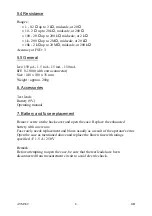
Page 9: ...48 x 100 x 35 mm Weight approx 280g 6 Accessories Test leads Battery 9V Operating manual 7 Battery and fuse replacement Remove screw on the back cover and open the case Replace the exhausted battery with a new one Fuse rarely needs replacement and blows usually as a result of the operator s error Open the case as mentioned above and replace the blown fuse with ratings specified F 1 5 A 250 V Remar...

Reviews: