DVM345DI GB
3
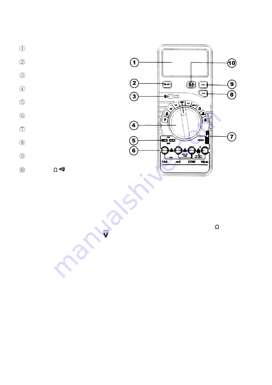
3.6. Description of the Front Panel
Display
"ON/OFF" push button
Transistor socket
Function switch
Capacitance or temperature socket
Input jacks
RS232C socket
"B/L"-button
"R-H" button
DC/AC- or
-button
4. OPERATION
4.1. Voltage Measurements
1. Connect the black test lead to the "COM"-
MDFNDQGWKHUHGWHVWOHDGWRWKH9
-jack.
2. Place the function switch in the -position and connect the test leads to the source you wish
to measure.
3. Select the VDC- or VAC-mode with the "DC/AC"-button (push "R-H" for manual range
selection).
4. The measured value will be displayed on the LCD. The polarity of the red test lead is
indicated with DC measurements.
4.2. Current Measurements
1. Connect the black test lead to the "COM"-jack and the red test lead to the "mA"-jack for
measurements up to 400mA. Switch the red test lead to the "10A"-jack for measurements up
to 10A.
2. Place the function switch in the "4mA"-, "400mA"- or "10A"-position and use the "DC/AC"-
button to select either the DCA- or the ACA-mode.
3. Connect the test leads in series with the load in which the current is to be measured.
4. The measured value will be displayed on the LCD. The polarity of the red test lead is
indicated with DC measurements.


