DVM645BI GB
14
Red
Circuit
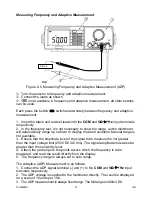
Measuring Frequency and Adaptive Measurement
Figure 2-5. Measuring Frequency and Adaptive Measurement (ADP)
c
Turn the selector to frequency and adaptive measurement.
d
Connect the leads as shown
e
is not available in frequency and adaptive measurement, all other buttons
can be used.
Each press the button
switches alternately between frequency and adaptive
measurement.
1. Insert the black and red test leads into the
COM
and
V
Ω
Ω
Ω
Ω
Hz
input terminals
respectively.
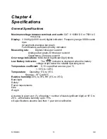
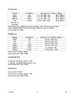
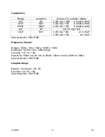
2. In the frequency test, it is not necessary to know the range, as the multimeter
will automatically range up or down to display the best resolution. Manual range is
not available.
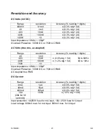
3. Ensure that the amplitude level of the signal to be measured is not greater
than the input voltage limit (250V DC/AC rms). The signal amplitude must also be
greater than the sensitivity level.
4. Attach the probe tips to the points across which the frequency is to be
measured, and read the result directly from the display.
5. The frequency range is always set to auto range.
The Adaptive (ADP) Measurement is as follows:
1. Connect the ADP signal terminal (-) and (+) to the
COM
and
V
Ω
Ω
Ω
Ω
Hz
input
terminals respectively.
2. The ADP voltage is supplied to the multimeter directly. The result is displayed
on a scale of 10 units per 1mV.
3. The ADP measurement is always fixed range. The full range is 400mV DC.


