DVM645BI GB
16
Red
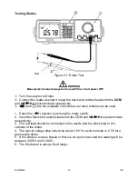
Testing Diodes
Figure 2-7. Diode Test
WARNING
Measurements must always be done with the circuit power OFF.
c
Turn the selector to Diode.
d
Connect the leads as shown: insert the black and red test leads into the
COM
and
V
Ω
Ω
Ω
Ω
Hz
input terminals respectively.
e
and
are not available in diode test, all other buttons can be used.
1. Select the (
) position by turning the rotary switch.
2. Insert the black and red test leads into the COM and
V
Ω
Ω
Ω
Ω
Hz
input terminals
respectively.
3. The red lead should be connected to the anode and the black lead to the
cathode of the diode.
4. The typical voltage drop should be about 0.6V for a silicon diode or 0.3V for a
germanium diode.
5. If the diode is reverse biased or there is an open circuit and the reading will be
between 3.000V and 3.400V.
6. The Diode test is always fixed range.

