DVM645BI GB
5
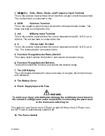
1. V
Ω
Ω
Ω
Ω
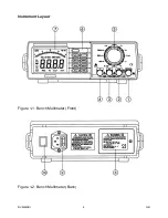
Hz Volts, Ohms, Diode, and Frequency Input Terminal
This is the positive input terminal for all functions except current measurement.
The red test lead is connected to this.
2. COM
Common Terminal
This is the negative (ground) input terminal for all measurement modes. The
black test lead is connected to this.
3. mA
Milliamp Input Terminal
This is the positive input terminal for current measurements (AC or DC) up to
400mA. The red test lead is connected to this.
4. A
10 Amp Input Terminal
This is the positive input terminal for current measurements (AC or DC) up to
10A. The red test lead is connected to this.
5. Function / Range Selector Rotary Switch
This rotary switch selects the function, and selects the desired range.
6. Function / Range Selector Buttons
This button selects the function, and selects the desired range.
7. The LCD Display
The LCD display indicates the measured value of a signal, the function mode,
and indicators.
8. The Battery Cover
9. Power Supply Input with Fuse
WARNING
To avoid user injury and multimeter damage, the multimeter must be set to
the same AC voltage value as the mains before connecting the power lead
to the mains and switching on.
This switch is used to turn the AC Power on and off. When the AC Power is on,
the DC Power is automatically switched off.
10. The Power Switch


