background image


DVM894 

V. 01 – 21/01/2015 

©Velleman nv 

USER MANUAL 

1.


Introduction 

To all residents of the European Union 

Important environmental information about this product 

This symbol on the device or the package indicates that disposal of the 
device after its lifecycle could harm the environment. Do not dispose of 
the unit (or batteries) as unsorted municipal waste; it should be taken to 

a specialized company for recycling. This device should be returned to 
your distributor or to a local recycling service. Respect the local 
environmental rules. 

If in doubt, contact your local waste disposal authorities. 

Thank you for choosing Velleman! Please read the manual thoroughly before 
bringing this device into service. If the device was damaged in transit, do not 
install or use it and contact your dealer. 
Refer to the 

Velleman® Service and Quality Warranty 

on the last pages of this 

manual. 

2.


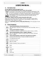
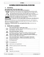
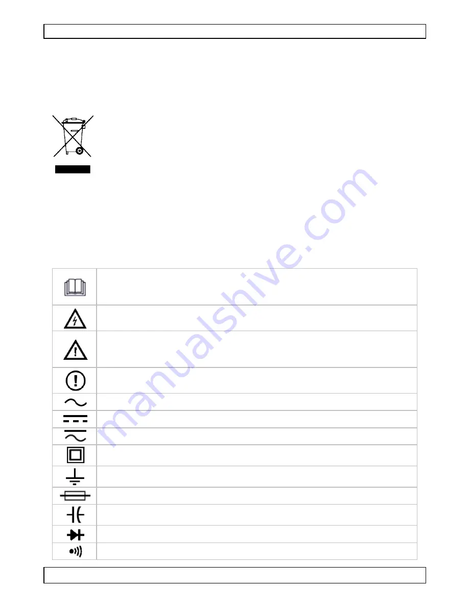
Used Symbols 


This symbol indicates: Read instructions. 

Not reading the instructions and manual can lead to damage, injury or 
death. 


This symbol indicates: Danger. 

A hazardous condition or action that may result in injury or death. 


This symbol indicates: Risk of danger/damage. 

Risk of a hazardous condition or action that may result in damage, 
injury or death. 


This symbol indicates: Attention; important information. 

Ignoring this information can lead to hazardous situations. 


AC (Alternating Current) 

  DC (Direct Current) 


Both AC and DC 


Double insulation (class 2-protection) 


Earth 

  Fuse 


Capacitor 


Diode 


Continuity 

Summary of Contents for DVM894

Page 1: ...RE NUMÉRIQUE 3 DIGITS 32 GAMMES MULTÍMETRO DIGITAL DE 3 32 RANGO 3 STELLIGES MULTIMETER 32 BEREICHE MULTIMETR CYFROWY LCD 3 32 OPCJE 3 DMM 32 NÍVEIS USER MANUAL 3 GEBRUIKERSHANDLEIDING 17 MODE D EMPLOI 32 MANUAL DEL USUARIO 47 BEDIENUNGSANLEITUNG 61 INSTRUKCJA OBSŁUGI 76 MANUAL DO UTILIZADOR 92 ...

Page 2: ...DVM894 V 01 21 01 2015 2 Velleman nv ...

Page 3: ...ad the manual thoroughly before bringing this device into service If the device was damaged in transit do not install or use it and contact your dealer Refer to the Velleman Service and Quality Warranty on the last pages of this manual 2 Used Symbols This symbol indicates Read instructions Not reading the instructions and manual can lead to damage injury or death This symbol indicates Danger A haz...

Page 4: ...This is an installation category CAT III 600V measuring instrument Never use this equipment in a higher category than indicated Refer to 4 Overvoltage installation category Pollution degree 2 device For indoor use only Keep this device away from rain moisture splashing and dripping liquids Not for industrial use Refer to 5 Pollution degree For your safety use only the test leads supplied with the ...

Page 5: ...xtreme caution when working around bare conductors or bus bars Do not operate the meter near explosive gases vapour or dust Verify the meter s operation by measuring a known voltage Do not use the meter if it operates abnormally Protection may be impaired When in doubt have the meter serviced by a qualified technician Make sure the device cannot be used until it is repaired When making connections...

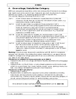
Page 6: ... fuse boxes lighting circuits electric ovens CAT IV A CAT IV rated meter is suitable for measuring in CAT I CAT II and CAT III environments as well as on the primary supply level Note that for all measurements on equipment for which the supply cables run outdoors either overhead or underground a CAT IV meter must be used Warning This device was designed in accordance with EN 61010 1 installation c...

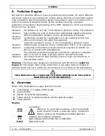
Page 7: ...o be expected industrial environments and environments exposed to outside air but not in contact with precipitation Pollution degree 4 The pollution generates persistent conductivity caused by conductive dust or by rain or snow exposed outdoor environments and environments where high humidity levels or high concentrations of fine particles occur Warning This device was designed in accordance with ...

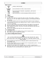
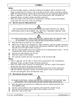
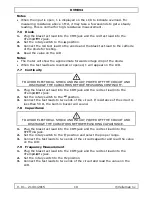
Page 8: ...Choose the highest range when the value to be measured is unknown 5 When making connection connect the common test lead first and then the powered test lead 6 Remove the charged test lead first when disconnecting 7 2 Readings Hold 1 Press HOLD to hold the reading of the current measurements 2 Press HOLD again to release the reading 7 3 AC DC Voltage Measurement USE CAUTION WHEN MEASURING HIGH VOLT...

Page 9: ...measured is between 200 mA and 10 A plug the red test lead into the 10A jack 3 Set the rotary switch to the A position for DC measurement and A for AC measurement Select the proper range 4 Connect the test leads to the circuit 5 Read the value on the display 6 The polarity symbol denotes the polarity of the red test lead Notes When 1 appears on the LCD it means the measurement has exceeded the all...

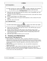
Page 10: ...AND DISCHARGE THE CAPACITORS BEFORE MEASURING CONTINUITY 1 Plug the black test lead into the COM jack and the red test lead into the VTempΩ Hz jack 2 Set the rotary switch to the position 3 Connect the test leads to two ends of the circuit If resistance of the circuit is less than 50 Ω the built in buzzer will sound 7 8 Capacitance TO AVOID ELECTRICAL SHOCK AND INJURY POWER OFF THE CIRCUIT AND DIS...

Page 11: ... hFE position and select the proper range 3 Determine if the transistor to be tested is either an NPN or PNP type then insert the three pins of the transistor into the corresponding holes of the multi function socket 4 Read the approximate transistor gain on the LCD 8 Cleaning and Maintenance Instructions for Safe Maintenance Meter calibration maintenance repair and other operations can only be pe...

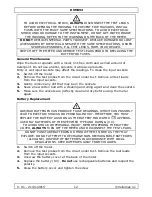
Page 12: ...input sockets 3 Gently remove any dirt that may be in the sockets 4 Soak a new cotton bud with a cleaning and oiling agent and clean the sockets 5 Make sure the sockets are perfectly clean and dry before using the meter again Battery Replacement LOW BAD BATTERIES CAN PRODUCE FALSE READINGS WHICH CAN POSSIBLY LEAD TO ELECTRIC SHOCKS OR PERSONAL INJURY THEREFORE YOU MUST REPLACE THE BATTERY AS SOON ...

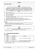
Page 13: ...ocated at the bottom of the PCB 5 Replace the blown fuse with a fuse of the same type and rating 6 Close the housing and tighten the screws Put the protective cover back 7 Place the battery back and close the battery cover Storage Remove the batteries from the device if it will not be used for a long time Old batteries can begin to leak and damage the device Do not store the device in a high tempe...

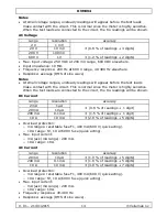
Page 14: ...with the circuit This is normal since the meter is highly sensitive When the test leads are connected to the circuit the tru readings will be shown DC Current range resolution accuracy 2 mA 1 µA 0 8 of readings 1 digit 20 mA 10 µA 200 mA 0 1 mA 1 5 of readings 1 digit 10 A 10 mA 2 0 of readings 5 digits Overload protection o mA ranges resettable fuse F1 400 mA 600 V quick acting o 10 A range F2 10...

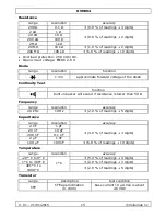
Page 15: ...the diode Continuity Test function built in buzzer will sound if resistance is lower than 50 Ω Frequency range resolution accuracy 20 kHz 10 Hz 2 0 of readings 5 digits Capacitance range resolution accuracy 2 nF 1 pF 4 0 of readings 3 digits 20 nF 10 pF 200 nF 0 1 nF 2 µF 1 nF 100 µF 100 nF 6 0 of readings 10 digits Temperature range resolution accuracy 20 C to 0 C 1 C 5 0 of readings 4 digits 1 C...

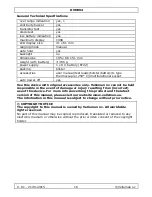
Page 16: ... multifunctional socket auto power off yes Use this device with original accessories only Velleman nv cannot be held responsible in the event of damage or injury resulting from incorrect use of this device For more info concerning this product and the latest version of this manual please visit our website www velleman eu The information in this manual is subject to change without prior notice COPY...

Page 17: ...ndleiding grondig voor u het toestel in gebruik neemt Werd het toestel beschadigd tijdens het transport installeer het dan niet en raadpleeg uw dealer Raadpleeg de Velleman Service and Quality Warranty achteraan deze handleiding 2 Gebruikte symbolen Dit symbool betekent Instructies lezen Het niet lezen van deze instructies en de handleiding kan leiden tot beschadiging letsel of de dood Dit symbool...

Page 18: ...escherm tegen schokken Vermijd brute kracht tijdens de bediening Vermijd koude hitte en grote temperatuurschommelingen Als het toestel van een koude naar een warme omgeving verplaatst wordt laat het toestel dan eerst voldoende op temperatuur komen Dit om meetfouten en condensvorming te vermijden Dit is een meetinstrument voor installatie categorie CAT III 600V Gebruik dit toestel nooit in een hoge...

Page 19: ...door accessoires van hetzelfde type met dezelfde specificaties Bestel reserveaccessoires zoals testdraden bij uw dealer Schakel de meter uit en verwijder de testdraden vóór u de batterij of zekeringen vervangt Om veiligheidsredenen mag u geen wijzigingen aanbrengen Schade door wijzigingen die de gebruiker heeft aangebracht valt niet onder de garantie Indien de meter gebruikt wordt in de nabijheid ...

Page 20: ...r is geschikt voor metingen op beschermde elektronische circuits die niet rechtstreeks verbonden zijn met het lichtnet bv elektronische schakelingen stuursignalen CAT II Een CAT II meter is geschikt voor metingen in CAT I omgevingen en op enkelfasige apparaten die aan het lichtnet gekoppeld zijn door middel van een stekker en circuits in een normale huiselijke omgeving op voorwaarde dat het circui...

Page 21: ... de isolatie en de eigenschappen van de behuizing De opgegeven waarde van vervuilingsgraad geeft aan in welke omgeving dit apparaat veilig gebruikt kan worden Vervuilingsgraad 1 Omgeving zonder of met enkel droge niet geleidende vervuiling De voorkomende vervuiling heeft geen invloed komt enkel voor in hermetisch afgesloten omgevingen Vervuilingsgraad 2 Omgeving met enkel niet geleidende vervuilin...

Page 22: ...ingen 10A ingangsaansluiting voor stroomwaarden tussen 200 mA en 10 A 7 Gebruik 7 1 Voorbereiding 1 Schakel de meter in door de draaischakelaar te draaien Indien de batterijspanning lager is dan 7 V zal het lege batterij symbool verschijnen en moeten de batterijen vervangen worden 2 Het waarschuwingssymbool naast de ingangsdraad wijst erop dat de ingangsspanning of stroom de specifieke waarde niet...

Page 23: ...erschijnen de tru meetwaarden Wanneer 1 verschijnt op het LCD scherm betekent dit dat de meting het toegelaten meetbereik overschreden heeft Er moet een hoger bereik geselecteerd worden Wanneer de te meten schaalwaarde onbekend is selecteert u eerst het hoogste bereik en verlaagt u het bereik 7 4 AC DC Stroommeting WEES VOORZICHTIG BIJ HET METEN VAN HOOGSPANNINGSCIRCUITS OM ELEKTRISCHE SCHOKKEN EN...

Page 24: ...r op Ω en selecteer het gepaste bereik 3 Verbind de testdraden met de uiteinden van de weerstand of met het circuit 4 Lees de waarde af op het LCD display Opmerkingen Bij een geopende ingang verschijnt 1 op het LCD display om te waarschuwen voor overbelasting Voor het meten van weerstanden hoger dan 1 MΩ kan het enkele seconden duren vooraleer u een stabiele meting verkrijgt Dit is normaal voor me...

Page 25: ...e rode testdraad in de VTempΩ Hz bus 2 Zet de draaischakelaar op Hz 3 Verbind de twee testdraden met twee uiteinden van het circuit en lees de waarde af op het LCD display 7 10 Temperatuur OM ELEKTRISCHE SCHOKKEN EN VERWONDINGEN TE VERMIJDEN GEEN OPPERVLAKKEN METEN VAN OBJECTEN MET EEN ELEKTRISCHE POTENTIAAL HOGER DAN 600 VDC 24 VAC 1 Steek de multifunctionele adapter met het IN uiteinde in de hFE...

Page 26: ...en OM ELEKTRISCHE SCHOKKEN TE VERMIJDEN VERWIJDER ALTIJD DE TESTDRADEN ALVORENS DE BEHUIZING TE OPENEN OM BRAND TE VOORKOMEN GEBRUIK ENKEL ZEKERINGEN MET DEZELFDE SPECIFICATIES OM ELEKTRISCHE SCHOKKEN EN OF BESCHADIGING AAN HET INSTRUMENT TE VERMIJDEN VERMIJD WATER INSIJPELING IN DE BEHUIZING ZIE WAARSCHUWING OP ACHTERKANT METER DE GEBRUIKER MAG GEEN INWENDIGE ONDERDELEN VERVANGEN VERVANG BESCHADI...

Page 27: ...r 4 Vervang de batterij 9 V Gebruik geen herlaadbare batterijen en respecteer de polariteit 5 Sluit het batterijdeksel en draai de schroef vast De zekering vervangen Gebruik enkel zekeringen van hetzelfde type met dezelfde specificaties en snelheid F250mA 250V F10A 500V keramisch ZEKERINGEN MOETEN SLECHTS ZELDEN WORDEN VERVANGEN EN EEN KAPOTTE ZEKERING IS BIJNA ALTIJD HET GEVOLG VAN EEN MENSELIJKE...

Page 28: ...ingangsspanning 250 VDC bij 200 mV 600 VDC elders Ingangsimpedantie 10 MΩ Opmerkingen Bij een klein spanningsbereik verschijnen onstabiele meetresultaten vooraleer de testdraden contact maken met het circuit Dit is normaal aangezien de meter zeer gevoelig is Wanneer de testdraden verbonden zijn met het circuit verschijnen de tru meetwaarden Wisselspanning bereik resolutie nauwkeurigheid 2 V 1 mV 0...

Page 29: ...µA 1 0 van de waarden 5 cijfers 200 mA 0 1mA 1 8 van de waarden 5 cijfers 10 A 10 mA 3 0 van de waarden 7 cijfers Beveiligd tegen overbelasting o ma bereik herinstelbare zekering F1 400 mA 600 V snelle reactie o 10 A bereik F2 10 A 600 V zekering snelle reactie Max ingangsstroom o mA bus mA bereik 200 mA o 10 A bereik 10 A Frequentierespons 40 400 Hz Respons gemiddeld sinusgolf RMS Weerstand berei...

Page 30: ...ur bereik resolutie nauwkeurigheid 20 C naar 0 C 1 C 5 0 van de waarden 4 cijfers 1 C naar 400 C 2 0 van de waarden 3 cijfers 401 C naar 1000 C 2 0 van de waarden 5 cijfers Transistor bereik omschrijving meetvoorwaarde hFE hFE benadering 0 1000 basisstroom 10 µA Vce is c a 2 8 VDC Algemene Technische specificaties buiten bereik indicatie ja 1 continuïteitszoemer ja transistortest ja diodetest ja b...

Page 31: ...ik van dit toestel Voor meer informatie over dit product en de laatste versie van deze handleiding zie www velleman eu De informatie in deze handleiding kan te allen tijde worden gewijzigd zonder voorafgaande kennisgeving AUTEURSRECHT Velleman nv heeft het auteursrecht voor deze handleiding Alle wereldwijde rechten voorbehouden Het is niet toegestaan om deze handleiding of gedeelten ervan over te ...

Page 32: ...ment le présent mode d emploi avant la mise en service de l appareil Si l appareil a été endommagé pendant le transport ne pas l installer et consulter votre revendeur Se référer à la garantie de service et de qualité Velleman en fin de notice 2 Symboles utilisés Ce symbole indique Lire les instructions Ne pas lire les instructions ou la notice peut causer des endommagements ou blessures ou entraî...

Page 33: ... Protéger du froid de la chaleur et des larges variations de température Attendre jusqu à ce que l appareil ait atteint la température ambiante lorsqu il est déplacé d un endroit froid à un endroit chaud Pour éviter la condensation et les erreurs de mesure Il s agit d un outil de mesure de catégorie d installation CAT III 600V Ne jamais utiliser cet appareil dans une catégorie supérieure à celle i...

Page 34: ...Préconiser l utilisation d un filtre téléviseur pour atténuer ces impulsions Ne pas remplacer les composants internes Remplacer les accessoires endommagés ou égarés par des accessoires avec des spécifications identiques Commander ces accessoires chez votre revendeur Éteindre le multimètre et retirer les sondes de mesure avant de remplacer les piles ou les fusibles Toute modification est interdite ...

Page 35: ...e surtension transitoire est une augmentation éphémère de la tension induite dans un système p ex causée par la foudre sur une ligne électrique Les catégories existantes selon EN 61010 1 sont CAT I Un multimètre classé CAT I convient au mesurage de circuits électroniques protégés non connectés directement au secteur électrique p ex connexions électroniques circuits signaux de contrôle CAT II Un mu...

Page 36: ...gré de pollution La norme IEC 61010 1 spécifie les différents types de pollution environnementale chaque type nécessitant son propre niveau de protection afin de garantir la sécurité Un environnement rude nécessite un niveau de protection plus sévère Le niveau de protection adapté à un environnement précis dépend de l isolation et de la qualité du boîtier Le degré de pollution du DMM indique l env...

Page 37: ... négative HV symbole de haute tension 600 VCA ou 600 VCC HOLD mode data hold Connexion d entrée COM borne d entrée commune Hz TEMP borne d entrée pour tout autre mesurage mA hFE borne d entrée pour des mesurages de transistor de capacité et de courant 10A borne d entrée pour courants d entre 200 mA et 10 A 7 Utilisation 7 1 Préparation 1 Tourner le sélecteur rotatif pour allumer le multimètre Quan...

Page 38: ... cordons de mesure soient connectés avec le circuit Ceci est normal puisque le multimètre est extrêmement sensible Les valeurs tru seront affichées dès que les cordons de mesure sont connectés au circuit Affichage de 1 sur l écran LCD la mesure a dépassé la gamme Une gamme supérieure est requise Lorsque l échelle de la valeur à mesurer est inconnue d abord sélectionner la gamme maximale et ensuite...

Page 39: ... Hz 2 Mettre le sélecteur rotatif en position Ω et sélectionner la gamme appropriée 3 Brancher les cordons de mesure sur les extrémités de la résistance ou du circuit 4 Lire la valeur sur l écran LCD Notes Lorsque l entrée est ouverte 1 est affiché sur l écran LCD pour indiquer la surcharge Pour mesurer une résistance 1 MΩ une lecture stable sera affichée après quelques secondes Ceci est normal en...

Page 40: ...nnecteur COM et le câble de mesure rouge dans le connecteur VTempΩ Hz 2 Mettre le sélecteur rotatif en position Hz 3 Brancher les cordons de mesure sur 2 extrémités du circuit et lire la valeur sur l écran LCD 7 10 Température POUR ÉVITER LES CHOCS ÉLECTRIQUES ET LES BLESSURES NE PAS MESURER LA SURFACE DE L OBJET AVEC UN POTENTIEL ÉLECTRIQUE SUPÉRIEUR À 60 VCC 24 VCA 1 Insérer la borne multifoncti...

Page 41: ...nsateurs du multimètre même après l extinction POUR ÉVITER LES CHOCS ÉLECTRIQUES TOUJOURS DÉCONNECTER LES CORDONS DE MESURE AVANT D OUVRIR LE BOÎTIER Pour éviter tout risque d incendie ne remplacer le fusible que par un exemplaire identique POUR ÉVITER LES CHOCS ÉLECTRIQUES ET OU DES ENDOMMAGEMENTS ÉVITER QU UN LIQUIDE PÉNÈTRE DANS LE BOÎTIER REMARQUE SE RÉFÉRER À L ARRIÈRE DE L APPAREIL Ne pas re...

Page 42: ...s piles rechargeables et respecter la polarité 5 Refermer le compartiment à piles et serrer la vis Remplacer le fusible N UTILISER QUE LES FUSIBLES SPÉCIFIÉS TYPE RATING VITESSE F250MA 250 V F10A 500 V CÉRAMIQUE IL EST RARE QUE LE FUSIBLE DOIT ÊTRE REMPLACÉ ET DANS LA PLUPART DES CAS UNE FAUTE D UTILISATEUR EST À LA BASE D UN FUSIBLE GRILLÉ POUR ÉVITER LES RISQUES D ÉLECTROCHOCS OU DES ENDOMMAGEME...

Page 43: ...ont avant que les cordons de mesure soient connectés avec le circuit Ceci est normal puisque le multimètre est extrêmement sensible Les valeurs tru seront affichées dès que les cordons de mesure sont connectés au circuit Tension CA gamme Résolution précision 2 V 1 mV 0 8 affichage 3 digits 20 V 10 mV 200 V 100 mV 600 V 1 V 1 2 affichage 2 digits Tension d entrée max 250 VCC à 200 mV 600 VCC ailleu...

Page 44: ...ffichage 5 digits 10 A 10 mA 3 0 affichage 7 digits Protection de surcharge o gammes mA fusible réarmable F1 400 mA 600 V action rapide o gamme 10 A F2 10 A 600 V fusible action rapide Courant d entrée max o connecteur mA gamme mA 200 mA o gamme 10 A 10 A Réponse de fréquence 40 400 Hz Réponse moyenne RMS ou onde sinusoïdale Résistance gamme Résolution précision 200 Ω 0 1 Ω 0 8 affichage 3 digits ...

Page 45: ...lution précision 20 C à 0 C 1 C 5 0 affichage 4 digits 1 C à 400 C 2 0 affichage 3 digits 401 C à 1000 C 2 0 affichage 5 digits Transistor gamme Description tester la condition hFE approximation hFE 0 1000 courant de base 10 µA Vce env 2 8 VCC Spécifications techniques générales indication hors plage oui 1 continuité du buzzer oui test de transistor oui test de diode oui indication de pile faible ...

Page 46: ... indirects pouvant résulter de l utilisation de cet appareil Pour plus d informations concernant cet article et la dernière version de ce mode d emploi consulter notre site www velleman eu Toutes les informations présentées dans ce mode d emploi peuvent être modifiées sans notification préalable DROITS D AUTEUR SA Velleman est l ayant droit des droits d auteur de ce mode d emploi Tous droits mondi...

Page 47: ...anual antes de usar el aparato Si ha sufrido algún daño en el transporte no lo instale y póngase en contacto con su distribuidor Véase la Garantía de servicio y calidad Velleman al final de este manual del usuario 2 Símbolos utilizados Este símbolo indica Leer las instrucciones Si no lee las instrucciones o el manual del usuario puede dañar el aparato o sufrir heridas incluso morir Este símbolo in...

Page 48: ...za durante la operación No exponga el aparato al frío el calor ni grandes variaciones de temperatura No conecte el aparato si ha estado expuesto a grandes cambios de temperatura Espere hasta que el aparato llegue a la temperatura ambiente Esto para evitar la condensación y los errores de medición Se trata de un instrumento de medida categoría de instalación CAT III 600V Nunca utilice este equipo e...

Page 49: ...esto por ejemplo cables de prueba a su distribuidor Desactive el multímetro y saque las puntas de prueba antes de reemplazar pilas o fusibles Por razones de seguridad las modificaciones no autorizadas del aparato están prohibidas Los daños causados por modificaciones no autorizadas no están cubiertos por la garantía Si utiliza el aparato cerca de instrumentos que generan interferencias electromagn...

Page 50: ... etc CAT II Un DMM de la categoría CAT II es apto para la medición en un ambiente CAT I aparatos monofásicos conectados a la red eléctrica con un conector y circuitos en un ambiente doméstico normal a condición de que el circuito esté a una distancia mínima de 10 m de un ambiente CAT III o 20 m de un ambiente CAT IV Ejemplo alimentación de aparatos electrodomésticos y herramientas portátiles etc C...

Page 51: ...nde del aislamiento y la calidad de la caja El grado de contaminación del DMM indica el ambiente en el que se puede utilizar el DMM Grado de contaminación 1 Ausencia de contaminación o contaminación seca y sólo no conductora Contaminación no influenciable sólo en un ambiente herméticamente cerrado Grado de contaminación 2 Sólo contaminación no conductora De vez en cuando puede sobrevenir una condu...

Page 52: ...or capacitancia y mediciones de corriente 10A terminal de entrada para corrientes de entre 200 mA y 10 A 7 Uso 7 1 Preparación 1 Encienda el medidor girando el interruptor giratorio Si el voltaje de la batería es inferior a 7 V el símbolo de batería baja aparecerá y las pilas se deben reemplazar 2 El símbolo de advertencia al lado del cable de entrada de indica que la tensión de entrada o corrient...

Page 53: ...ados al circuito se mostrarán las lecturas reales Cuando 1 aparece en la pantalla LCD significa que la medida ha superado el rango permitido Un rango superior debe ser seleccionado Cuando la escala del valor a medir es desconocida debe seleccionar el rango más alto primero y bajar el rango en consecuencia 7 4 Medición de Corriente AC DC SEA PRECAVIDO AL MEDIR CIRCUITOS DE ALTO VOLTAJE PARA EVITAR ...

Page 54: ...e prueba a los terminales de la resistencia o circuito 4 Lea el valor en la pantalla LCD Observaciones Cuando la entrada está abierta 1 aparece en la pantalla LCD para indicar la sobrecarga Para medir una resistencia superior a 1 MW puede tardar unos segundos para obtener una lectura estable Esto es normal para la medición de alta resistencia 7 6 Diodo 1 Conecte el cable de prueba negro en la entr...

Page 55: ...or en la pantalla LCD 7 10 Temperature PARA EVITAR CHOQUE ELÉCTRICO Y LESIONES NO MEDIR LA SUPERFICIE DE UN OBJETO CON UN POTENCIAL ELÉCTRICO SUPERIOR A 60 VDC 24 VAC 1 Conecte la toma multifunción con el terminal IN en el conector Hz VTempΩ y el terminal COM en el conector COM 2 Inserte el termopar tipo K en la toma multifunción con la polaridad correcta 3 Coloque el interruptor giratorio en la p...

Page 56: ...NCIA EN LA PARTE TRASERA DEL METRO NO SUSTITUIR COMPONENTES INTERNOS USTED MISMO CAMBIAR ACCESORIOS DAÑADOS OU PERDIDOS POR OTROS IDÉNTICOS CON LAS MISMAS ESPECIFICACIONES PEDIR ACCESORIOS DE RECAMBIO PEDIDO POR EJEMPLO CABLES DE PRUEBA A SU DISTRIBUIDOR APAGUE EL MEDIDOR Y QUITE LOS CABLES DE PRUEBA ANTES DE LA SUSTITUCIÓN DE LA PILA O FUSIBLES Mantenimiento general Limpie el aparato regularmente...

Page 57: ...0MA 250 V F10A 500 V CERÁMICA EL FUSIBLE RARAMENTE NECESITA DE SER SUSTITUIDO Y UN FUSIBLE QUEMADO CASI SIEMPRE ES CAUSADO POR UN ERROR HUMANO PARA EVITAR CHOQUE O LESIONES PERSONALES ANTES DE ABRIR LA CAJA DEBE SIEMPRE APAGAR EL MEDIDOR Y DESCONECTAR LOS CABLES DE PRUEBA 1 Desactive el multímetro 2 Saque las puntas de prueba del circuito que quiere probar Saque las puntas de prueba de las entrada...

Page 58: ... las lecturas 2 dígitos Tensión de entrada máx 250 VDC en el rango 200 mV 600 VDC para otros Impedancia de entrada 10 MΩ Respuesta en frecuencia 200 Hz en el rango 600 V 40 400 Hz para otros Respuesta promedio RMS de onda sinusoidal Observaciones En rangos de tensión pequeños aparecerán lecturas inestables antes de que los cables de prueba estén en contacto con el circuito Esto es normal ya que el...

Page 59: ...ia alcance resolución precisión 200 Ω 0 1 Ω 0 8 de las lecturas 3 dígitos 2 kΩ 1 Ω 0 8 de las lecturas 2 dígitos 20 kΩ 10 Ω 200 kΩ 100 Ω 2 MΩ 1 kΩ 20 MΩ 10 kΩ 1 0 de las lecturas 2 dígitos 200 MΩ 100 kΩ 6 0 de las lecturas 10 dígitos Protección de sobrecarga 250 V AC DC Tensión circuito abierto DC 2 8 V Diodo alcance resolución Función 1 mV tensión directa aproximada del diodo Prueba de Continuida...

Page 60: ...as pilas 366 g alimentación 1 pila 9 V 6F22 embalaje ampolla accesorios manual del usuario cables de prueba funda pila termopar tipo K 250 C toma multifuncional desconexión automática sí Utilice este aparato sólo con los accesorios originales Velleman NV no será responsable de daños ni lesiones causados por un uso indebido de este aparato Para más información sobre este producto y la versión más r...

Page 61: ...tschieden haben Lesen Sie diese Bedienungsanleitung vor Inbetriebnahme sorgfältig durch Überprüfen Sie ob Transportschäden vorliegen Sollte dies der Fall sein verwenden Sie das Gerät nicht und wenden Sie sich an Ihren Händler Siehe Velleman Service und Qualitätsgarantie am Ende dieser Bedienungsanleitung 2 Verwendete Symbole Dieses Symbol bedeutet Bitte lesen Sie die Hinweise Das nicht Lesen der H...

Page 62: ...technische Daten Bemerkung dies ist die Übersetzung der Warnung die sich auf der Rückseite des Gerätes befindet Halten Sie Kinder und Unbefugte vom Gerät fern Vermeiden Sie Erschütterungen Vermeiden Sie rohe Gewalt während der Bedienung Setzen Sie das Gerät keiner Kälte Hitze und großen Temperaturschwankungen aus Nehmen Sie das Gerät nicht sofort in Betrieb nachdem es von einem kalten in einen war...

Page 63: ...brauch der 10A Buchse Messen Sie keinen Strom in Kreisen mit einer Spannung 500 V Sorgen Sie dafür dass die Schaltung spannungslos ist und dass alle Kondensatoren völlig entladen sind ehe Sie Widerstand Durchgang Kapazität oder Dioden messen Verwenden Sie für die Transistortests den mitgelieferten Sockel Bei TV Reparaturarbeiten oder Messungen an Schaltkreisen können die hohen Spannungsimpulse in ...

Page 64: ... Das Gerät funktioniert mit einer 9 V Batterie Legen Sie diese polungsrichtig in das Batteriefach ein Wechseln Sie bitte die Batterie sobald die Batterieanzeige erscheint So vermeiden Sie ungenaue Messergebnisse die Stromschläge oder Verletzungen verursachen können Verwenden Sie das Multimeter nicht wenn das Gehäuse völlig oder zum Teil entfernt ist Überprüfen Sie vor jeder Messung ob die Anschlüs...

Page 65: ...essungen an Steckdosen Elektroherd Beleuchtungskreisen Stromschienen Sicherungen und Leistungsschalter Das Gerät eignet sich nicht für Spannungen höher als 1000 V Messungen an Niederspannungsverteilungen und Außenanlagen Diese enthalten Zählerkasten und Geräte Kreise im Außenbereich oder unabhängig von der häuslichen Umgebung wie z B Kreise in Scheunen Gartenhäuschen und allein stehenden Garagen o...

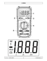
Page 66: ...t werden verursacht wird Warnung Das Gerät wurde gemäß EN 61010 1 Verschmutzungsgrad 2 entworfen Dies beinhaltet bestimmte Anwendungsbeschränkungen in Bezug auf die Verschmutzungsgrad die in der Gebrauchsumgebung vorkommen kann Siehe Liste oben DIESES GERÄT EIGNET SICH NUR FÜR MESSUNGEN IN DER UMGEBUNG IN DER VERSCHMUTZUNGSGRADKLASSE 2 6 Beschreibung Siehe Abbildungen Seite 2 dieser Bedienungsanle...

Page 67: ...ch wählen 5 Beim Anschließen zunächst das gemeinsame Messkabel und dann das spannungsführende Messkabel anschließen 6 Beim Trennen der Leitungen zuerst das belastete Messkabel entfernen 7 2 Anzeigen halten 1 HOLD betätigen um die Anzeige für die aktuellen Messungen zu halten 2 HOLD erneut betätigen um die Anzeige freizugeben 7 3 AC DC Spannungsmessung GEHEN SIE VORSICHTIG BEI MESSUNGEN AN HOCHSPAN...

Page 68: ...COM Buchse 2 Für Strommessungen im Messbereich unter 200 mA stecken Sie das rote Messkabel in die mA Buchse Für Strommessungen im Messbereich zwischen 200 mA und 10 A stecken Sie das rote Messkabel in die 10A Buchse 3 Stellen Sie den Drehschalter auf A Position für DC Messungen und auf A für AC Messungen Entsprechenden Messbereich wählen 4 Schließen Sie die Messkabel an den Messkreis an 5 Wert auf...

Page 69: ...Anode und das schwarze Messkabel an die Katode der zu prüfenden Diode an 4 Wert auf der LCD Anzeige ablesen Bemerkungen Das Messgerät soll den angenäherten Flussspannungsabfall auf der Diode anzeigen Wenn die Messkabel vertauscht oder offen sind erscheint 1 auf dem LCD 7 7 Durchgang UM VERLETZUNGEN DURCH ELEKTRISCHEN SCHLAG ZU VERMEIDEN VOR KABELBRUCHMESSUNG DEN STROMKREIS ABSCHALTEN UND DIE KONDE...

Page 70: ...t ein 3 Stellen Sie den Drehschalter auf die TEMP Position 4 Mittels des Thermoelements die Temperatur der Prüfobjektoberfläche messen 5 Wert auf der LCD Anzeige ablesen 7 11 Transistorverstärkung UM VERLETZUNGEN DURCH ELEKTRISCHEN SCHLAG ZU VERMEIDEN TESTEN SIE NICHT MIT SPANNUNGEN DIE 250 V AC DC ÜBERSCHREITEN 1 Stecken Sie den Mehrzweckanschluss mit dem IN Anschluss in die Buchse VTempΩ mA und ...

Page 71: ... AUSSCHALTEN UND DIE MESSKABEL ENTFERNEN Allgemeine Wartung Reinigen Sie das Gerät mit einem sauberen feuchten fusselfreien Tuch und ein bisschen Reinigungsmittel Verwenden Sie auf keinen Fall Alkohol irgendwelche Lösungsmittel oder Scheuermittel Nasse oder schmutzige Eingangsbuchsen können falsche Messergebnisse verursachen Die Eingangsbuchsen reinigen 1 Schalten Sie das Gerät aus 2 Trennen Sie d...

Page 72: ...FAST IMMER DURCH MENSCHLICHE FEHLER VERURSACHT UM VERLETZUNGEN DURCH ELEKTRISCHEN SCHLAG ZU VERMEIDEN IMMER DAS MESSGERÄT AUSSCHALTEN UND DIE MESSKABEL ENTFERNEN 1 Schalten Sie das Gerät aus 2 Trennen Sie die Messleitung vom Kreis Trennen Sie die Messleitungen von den Eingangsbuchsen 3 Entfernen Sie die Batterie 4 Entfernen Sie die Abdeckkappe lockern Sie die Schrauben auf der Rückseite des Geräte...

Page 73: ...mV 600 V 1 V 1 2 der Anzeige 2 Digits Max Eingangsspannung 250 VDC bei Messbereich 200 mV sonst 600 VDC Eingangsimpedanz 10 MΩ Frequenzgang 250 VDC bei Messbereich 600 V sonst 40 400 VDC Antwort Mittelwert Quadratmittel der Sinuswelle Bemerkungen Bei kleinen Spannungsbereichen erscheinen unstabile Anzeigen bevor die Messkabel den Stromkreis kontaktieren Dies ist normal da dieses Messgerät hochempf...

Page 74: ...Reichweite Auflösung Genauigkeit 200 Ω 0 1 Ω 0 8 der Anzeige 3 Digits 2 kΩ 1 Ω 0 8 der Anzeige 2 Digits 20 kΩ 10 Ω 200 kΩ 100 Ω 2 MΩ 1 kΩ 20 MΩ 10 kΩ 1 0 der Anzeige 2 Digits 200 MΩ 100 kΩ 6 0 der Anzeige 10 Digits Überlastschutz 250 V AC DC Offen Kreis Messspannung DC 2 8 V Dioden Reichweite Auflösung Funktion 1 mV Flussspannung Diode ca Leitungsbruchstest Funktion Eingebauter Summer wird aktivie...

Page 75: ...sorgung Batterie 1 x 9 V 6F22 Verpackung Blister Zubehör Bedienungsanleitung Messkabel Tasche Batterie K Typ Thermoelement 250 C Mehrzweckdose Autom Versorgungsspannung AUS ja Verwenden Sie dieses Gerät nur mit originellen Zubehörteilen Velleman NV übernimmt keine Haftung für Schaden oder Verletzungen bei falscher Anwendung dieses Gerätes Mehr Informationen zu diesem Produkt und die neueste Versio...

Page 76: ...ugi przed użyciem Jeśli urządzenie zostało uszkodzone podczas transportu nie należy go instalować ani używać prosimy o skontaktowanie się ze sprzedawcą Proszę zapoznać się z informacjami w części Usługi i gwarancja jakości Velleman na końcu niniejszej instrukcji 2 Zastosowane symbole Ten symbol wskazuje Zapoznać się z instrukcją obsługi Nieznajomość instrukcji obsługi może prowadzić do uszkodzenia...

Page 77: ...rzeżenie na tylnej części miernika Chronić urządzenie przed dziećmi i nieupoważnionymi użytkownikami Chronić urządzenie przed wstrząsami i użytkowaniem niezgodnym z przeznaczeniem Podczas obsługi urządzenia unikać używania siły Unikać zbyt niskich i wysokich temperatur jak również dużych wahań temperatury W przypadku przeniesienia urządzenia z zimnego do ciepłego miejsca pozostawić je wyłączone do...

Page 78: ...u parametrów obwodów znajdujących się pod napięciem należy zachować szczególną ostrożność Zachować szczególną ostrożność podczas pomiaru napięcia o wartościach przekraczających 60 VDC lub 30 VAC rms Gdy stosowana jest końcówka mA nie dokonywać pomiaru prądu w obwodach o napięciu 250 V Gdy stosowana jest końcówka 10A nie dokonywać pomiaru prądu w obwodach o napięciu 500 V Przed przystąpieniem do mi...

Page 79: ...zerwony a następnie przewód probierczy wspólny czarny Przed zmianą funkcji lub zakresu pomiarowego należy odłączyć przewody probiercze od obwodu który jest testowany W przypadku funkcji DC aby uniknąć ryzyka porażenia elektrycznego z powodu niewłaściwych odczytów należy najpierw sprawdzić obecność napięcia AC przy użyciu funkcji AC Następnie wybrać zakres napięcia DC równy lub wyższy niż zakres AC...

Page 80: ...dziemna lub podziemna bezwzględnie należy używać mierników kat IV Uwaga Niniejsze urządzenie zostało zaprojektowane z myślą o instalacji kategorii III 600 V zgodnie z normą EN 61010 1 Oznacza to że obowiązują pewne ograniczenia w zakresie stosowania urządzenia związane z napięciem i wzrostami napięcia które mogą wystąpić w stosowanych układach Patrz powyższa tabela Niniejsze urządzenie jest przezn...

Page 81: ...eń zanieczyszczenia III Występują zanieczyszczenia o właściwościach przewodzących lub zanieczyszczenia suche bez właściwości przewodzących które na skutek kondensacji mogą stać się przewodzące środowiska przemysłowe i mające kontakt z powietrzem zewnętrznym ale chronione przed działaniem opadów atmosferycznych Stopień zanieczyszczenia IV Zanieczyszczenia powodujące stałe przewodzenie prądu pyły pr...

Page 82: ...kaźnik niskiego poziomu baterii i należy wymienić baterie 2 Symbol ostrzegawczy obok przewodu wejściowego oznacza że wartość napięcia lub prądu wejściowego nie powinna przekraczać określonej wartości aby zapewnić ochronę wewnętrznego obwodu przed uszkodzeniem 3 Przekręcić pokrętło wybierając żądaną funkcję oraz zakres pomiarowy 4 Wybrać najwyższy zakres jeśli mierzona wartość jest nieznana 5 Podcz...

Page 83: ...eznana należy najpierw wybrać najwyższy zakres a następnie odpowiednio obniżyć 7 4 Pomiar prądu AC DC ZACHOWAĆ OSTROŻNOŚĆ PODCZAS POMIARU OBWODÓW WYSOKIEGO NAPIĘCIA ABY UNIKNĄĆ PORAŻENIA PRĄDEM ELEKTRYCZNYM ORAZ OBRAŻEŃ CIAŁA NIE DOKONYWAĆ POMIARÓW JEŚLI WARTOŚCI NAPIĘCIA SĄ WYŻSZE NIŻ 600 V AC DC ABY UNIKNĄĆ PORAŻENIA PRĄDEM ELEKTRYCZNYM ORAZ OBRAŻEŃ CIAŁA PRZED POMIAREM WARTOŚCI PRĄDU ODŁĄCZYĆ Z...

Page 84: ...ą wartość na wyświetlaczu Uwagi Przy otwartym wejściu na wyświetlaczu pojawi się cyfra 1 oznaczająca przeciążenie Podczas pomiaru rezystancji przekraczającej 1 MΩ uzyskanie stabilnego odczytu zajmuje kilka sekund Jest to typowe w przypadku pomiaru wysokiej rezystancji 7 6 Dioda 1 Podłączyć czarny przewód probierczy do gniazda COM a czerwony przewód probierczy do gniazda VTempΩ Hz 2 Ustawić pokrętł...

Page 85: ...krętło w pozycji Hz 3 Podłączyć przewody probiercze do dwóch końców obwodu i odczytać wartość pomiaru na wyświetlaczu 7 10 Temperatura ABY UNIKNĄĆ PORAŻENIA PRĄDEM ELEKTRYCZNYM ORAZ OBRAŻEŃ CIAŁA NIE MIERZYĆ POWIERZCHNI OBIEKTU O POTENCJALE ELEKTRYCZNYM WYŻSZYM NIŻ 60 VDC 24 VAC 1 Podłączyć gniazdo wielofunkcyjne z końcem IN do gniazda VTempΩ Hz a koniec COM do gniazda COM 2 Umieścić termoparę typ...

Page 86: ...odłączeniu od zasilania ABY UNIKNĄĆ PORAŻENIA PRĄDEM ELEKTRYCZNYM NALEŻY KAŻDORAZOWO ODŁĄCZAĆ PRZEWODY PROBIERCZE PRZED OTWARCIEM OBUDOWY ABY ZAPOBIEC ZAGROŻENIU POŻAROWEMU ZAINSTALOWAĆ BEZPIECZNIKI O TAKIEJ SAMEJ SPECYFIKACJI ABY UNIKNĄĆ PORAŻENIA PRĄDEM ELEKTRYCZNYM I LUB USZKODZENIA PRZYRZĄDU NALEZY ZAPOBIEGAĆ PRZEDOSTAWANIU SIĘ WODY DO WNĘTRZA OBUDOWY ZAPOZNAĆ SIĘ Z TREŚCIĄ OSTRZEŻENIA Z TYŁU ...

Page 87: ...ercze z gniazd wejściowych 3 Odkręcić pokrywę baterii znajdującą się z tyłu miernika 4 Wymienić baterię 9 V Nie stosować akumulatorków zwracać uwagę na biegunowość 5 Zamknąć pokrywę baterii i dokręcić śrubę Wymiana bezpiecznika STOSOWAĆ WYŁĄCZNIE BEZPIECZNIKI OKREŚLONEGO TYPU WARTOŚCI ZNAMIONOWEJ ORAZ PRĘDKOŚCI F250MA 250 V F10A 500 V CERAMICZNE BEZPIECZNIKI NIE WYMAGAJĄ CZĘSTEJ WYMIANY A ICH PRZE...

Page 88: ...200 V 100 mV 600 V 1 V 0 8 odczytu 2 cyfry Maks napięcie wejściowe 250 VDC przy zakresie 200 mV 600 VDC w innych miejscach Impedancja wejściowa 10 MΩ Uwagi Przy niskich zakresach napięcia zanim przewody probiercze zetkną się z obwodem pojawiające się odczyty będą niestabilne Jest to typowe z uwagi na wysoką wrażliwość multimetra Po podłączeniu przewodów probierczych do obwodu na wyświetlaczu pojaw...

Page 89: ...iałający Maks prąd wejściowy gniazdo o mA zakres mA 200 mA o Zakres 10 A 10 A Prąd zmienny AC zakres rozdzielczość dokładność 20 mA 10 µA 1 0 odczytu 5 cyfr 200 mA 0 1mA 1 8 odczytu 5 cyfr 10 A 10 mA 3 0 odczytu 7 cyfr Zabezpieczenie przeciążeniowe o zakresy mA bezpiecznik resetowalny F1 400 mA 600 V szybko działający o Zakres 10 A bezpiecznik resetowalny F2 10 mA 600 V szybko działający Maks prąd...

Page 90: ... dokładność 2 nF 1 pF 4 0 odczytu 3 cyfry 20 nF 10 pF 200 nF 0 1 nF 2 µF 1 nF 100 µF 100 nF 6 0 odczytu 10 cyfr Temperatura zakres rozdzielczość dokładność 20 C do 0 C 1 C 5 0 odczytu 4 cyfry 1 C do 400 C 2 0 odczytu 3 cyfry 401 C do 1000 C 2 0 odczytu 5 cyfr Tranzystor zakres opis warunki testowe hFE Wartość przybliżona hFE 0 1000 prąd bazy 10 µA Vce wynosi ok 2 8 VDC Ogólna specyfikacja technicz...

Page 91: ...u uszkodzeń lub obrażeń ciała powstałych w wyniku nieprawidłowej obsługi urządzenia Aby uzyskać więcej informacji dotyczących produktu oraz najnowszą wersję niniejszej instrukcji należy odwiedzić naszą stronę internetową www velleman eu Informacje zawarte w niniejszej instrukcji obsługi mogą ulec zmianie bez wcześniejszego powiadomienia INFORMACJA O PRAWACH AUTORSKICH Niniejsza instrukcja jest wła...

Page 92: ...nte as instruções do manual antes de usar o aparelho Caso o aparelho tenha sofrido algum dano durante o transporte não o instale e entre em contacto com o seu distribuidor Consulte a Garantia de serviço e qualidade Velleman na parte final deste manual do utilizador 2 Símbolos utilizados Este símbolo indica Ler instruções Não ler as instruções ou o manual pode levar à ocorrência de danos lesões ou ...

Page 93: ...a utilização Não exponha o aparelho ao frio calor e grandes variações de temperatura Ao deslocar o aparelho de um local frio para um local quente deixe o desligado até estar á temperatura ambiente Isto evitará a formação de condensação e erros de medição Este é um instrumento de medição de categoria CAT III 600V Nunca use este aparelho numa categoria superior à indicada Consulte 4 Sobretensão cate...

Page 94: ...à substituição de componentes internos Substitua os acessórios perdidos ou danificados por outros idênticos e com as mesmas especificações Encomende acessórios de substituição por ex cabos de teste ao seu fornecedor Desligue o multímetro e retire as pontas de teste antes de substituir as pilhas ou os fusíveis Por razões de segurança estão proibidas quaisquer modificações do aparelho desde que não ...

Page 95: ...aio num poste de alta tensão As categorias segundo o EN 61010 1 são CAT I Um multímetro de categoria CAT I é indicado para medir circuitos electrónicos protegidos não conectados directamente à rede eléctrica p ex ligações de circuitos electrónicos sinais de controlo CAT II Um multímetro de categoria CAT II é indicado para medições num ambiente CAT I aparelhos monofásicos ligados à rede eléctrica c...

Page 96: ... IEC 61010 1 especifica os diferentes tipos de contaminação ambiental Cada tipo necessita do seu próprio nível de protecção para garantir segurança Um ambiente rugoso necessita de um nível de protecção mais severo O nível de protecção adaptado a um determinado ambiente depende do isolamento e da qualidade da caixa O grau de contaminação do DMM indica o tipo de ambiente em que o mesmo pode ser util...

Page 97: ...laridade de entrada negativa HV símbolo de alta tensão 600 VAC ou 600 VDC HOLD modo retenção de dados Tomada de entrada COM terminal de entrada comum V Ω Hz TEMP terminal de entrada para todas as outras medições mA hFE terminal de entrada para transistor capacitância e medições de corrente 10A terminal de entrada para correntes entre 200 mA e 10 A 7 Utilização 7 1 Preparação 1 Ligue o medidor roda...

Page 98: ... sensível Quando os cabos de teste estão ligados ao circuito as leituras aparecem Quando aparece 1 no LCD significa que a medição excedeu a categoria selecionada Deve selecionar uma categoria superior Quando a escala do valor a ser medido é desconhecida selecione a categoria mais alta inicialmente e vá baixando conforme necessário 7 4 Medição de corrente AC DC TENHA MUITO CUIDADO AO MEDIR CIRCUITO...

Page 99: ... no visor Notas Quando a entrada está aberta aparece um 1 no ecrã para indicar sobrecarga Para medir uma resistência acima de 1 MΩ pode demorar alguns segundos até conseguir uma leitura estável Isto é normal na medição de resistências elevadas 7 6 Díodo 1 Ligue o cabo de teste preto na entrada COM e o cabo de teste vermelho na entrada VTempΩ Hz 2 Coloque o seletor giratório na posição 3 Ligue o ca...

Page 100: ...ÉTRICOS OU DANOS NÃO MEÇA A SUPERFÍCIE DO OBJETO COM UM POTENCIAL ELÉTRICO SUPERIOR A 60 VDC 24 VAC 1 Ligue a tomada multifunções com o terminal IN na entrada VTempΩ Hz e o terminal COM na entrada COM 2 Introduza o termopar tipo K na tomada multifunções respeitanto a polaridade 3 Rode o seletor para a posição TEMP 4 Use um termopar para medir a temperatura da superfíce do objeto a testar 5 Leia o ...

Page 101: ...INCÊNDIO INSTALE SEMPRE FUSÍVEIS COM AS MESMAS CARACTERÍSTICAS PARA EVITAR CHOQUES ELÉTRICOS E OU DANIFICAR O INSTRUMENTO NÃO DEIXE ENTRAR ÁGUA PARA DENTRO DO APARELHO LEIA O AVISO NA PARTE DE TRÁS DO MEDIDOR NÃO PROCEDA À SUBSTITUIÇÃO DE COMPONENTES INTERNOS Substitua os acessórios perdidos ou danificados por outros idênticos e com as mesmas especificações ENCOMENDE PEÇAS DE SUBSTITUIÇÃO POR EX C...

Page 102: ...Não use pilhas recarregáveis e respeite sempre a polaridade 5 Feche a tampa do compartimento das pilhas e aperte o parafuso Substituição do fusível USE APENAS FUSÍVEIS DO TIPO CLASSIFICAÇÃO E VELOCIDADE INDICADOS F250MA 250 V F10A 500 V CERÂMICO O FUSÍVEL RARAMENTE PRECISA DE SER SUBSTITUÍDO E UM FUSÍVEL QUEIMADO É NORMALMENTE CONSEQUÊNCIA DE ERRO HUMANO PARA EVITAR CHOQUES OU DANOS PESSOAS ANTES ...

Page 103: ... teste entrarem em contacto com o circuito Isto é normal uma vez que o medidor é extremamente sensível Quando os cabos de teste estão ligados ao circuito serão apresentadas as leituras reais voltagem AC Amplitude resolução Precisão 2 V 1 mV 0 8 da leitura 3 dígitos 20 V 10 mV 200 V 100 mV 600 V 1 V 1 2 da leitura 2 dígitos Máx tensão de entrada 250 VDC na categoria 200 mV 600 VDC para qualquer out...

Page 104: ...da leitura 5 dígitos 10 A 10 mA 3 0 da leitura 7 dígitos Protecção contra sobrecarga o nível mA ranges fusível reinicializável F1 400 mA 600 V acção rápida o nível 10 A F2 fusível 10 A 600 V acção rápida Corrente de entrada máx o entrada mA nível mA 200 mA o nível 10 A 10 A Frequência de resposta 40 400 Hz Resposta média RMS da onda senoidal Resistência Amplitude resolução Precisão 200 Ω 0 1 Ω 0 8...

Page 105: ...esolução Precisão 20 C a 0 C 1 C 5 0 da leitura 4 dígitos 1 C a 400 C 2 0 da leitura 3 dígitos 401 C a 1000 C 2 0 da leitura 5 dígitos Transistor Amplitude Descrição Condições de teste hFE aproximação hFE 0 1000 a corrente base 10 µA Vce é cerca de 2 8 VDC Especificações Técnicas Gerais indicador de sobretensão sim 1 indicador sonoro de continuidade sim teste de transistores sim teste de díodos si...

Page 106: ...elo uso indevido do aparelho Para mais informação sobre este produto e para aceder à versão mais recente deste manual do utilizador visite a nossa página www velleman eu Podem alterar se as especificações e o conteúdo deste manual sem aviso prévio DIREITOS DE AUTOR A Velleman NV detém os direitos de autor deste manual do utilizador Todos os direitos mundiais reservados É estritamente proibido repr...

Page 107: ...inds zijn oprichting in 1972 een ruime ervaring opgebouwd in de elektronicawereld en verdeelt op dit moment producten in meer dan 85 landen Al onze producten beantwoorden aan strikte kwaliteitseisen en aan de wettelijke bepalingen geldig in de EU Om de kwaliteit te waarborgen ondergaan onze producten op regelmatige tijdstippen een extra kwaliteitscontrole zowel door onze eigen kwaliteitsafdeling a...

Page 108: ...ctuée en dehors de la période de garantie fera l objet de frais de transport toute garantie commerciale ne porte pas atteinte aux conditions susmentionnées La liste susmentionnée peut être sujette à une complémentation selon le type de l article et être mentionnée dans la notice d emploi Garantía de servicio y calidad Velleman Desde su fundación en 1972 Velleman ha adquirido una amplia experiencia...

Page 109: ...schreibung hinzu Hinweis Um Kosten und Zeit zu sparen lesen Sie die Bedienungsanleitung nochmals und überprüfen Sie ob es keinen auf de Hand liegenden Grund gibt ehe Sie das Gerät zur Reparatur zurückschicken Stellt sich bei der Überprüfung des Gerätes heraus dass kein Geräteschaden vorliegt könnte dem Kunden eine Untersuchungspauschale berechnet Für Reparaturen nach Ablauf der Garantiefrist werde...

Page 110: ... de 1 ano depois da data de compra e entrega ou um artigo de substituição pagando o valor de 50 do preço de compra ou devolução de 50 do preço de compra para defeitos depois de 1 a 2 anos estão por consequência excluídos todos os danos directos ou indirectos depois da entrega do artigo p ex danos ligados a oxidação choques quedas poeiras areias impurezas e provocado pelo aparelho como o seu conteú...

Reviews: