background image

Construction 


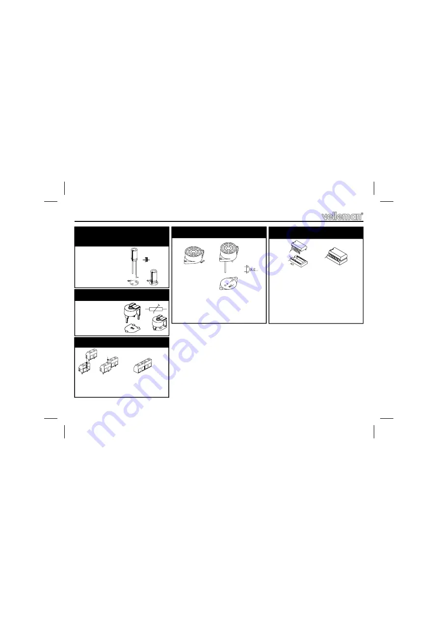
C6 : 470µF


7. Electrolytic capacitor.  
Watch the polarity !


C...


RV1 :  470K 


RV1

8. Trim Potentiometer


J1  :  2p + 2p 


J2  :  2p + 2p 

9. Screw connectors


BUZ1 


Be sure to put the longest 
connection into the bore 
marked 

‘+’


10. Buzzer


IC1 :  CD4060 or eq.


IC2 :  CD4020 or eq.


IC3 :  CD4068 or eq.


IC4 :  CD4093 or eq.


IC5 :  CD4049 or eq.


Pay attention to the position  

of the notch! 


11. IC’s mounting


PIN 1

1

Summary of Contents for High-Q Velleman-Kit K3502

Page 1: ...Parking Radar K3502 ILLUSTRATED ASSEMBLY MANUAL H3502IP 2 Total solder points 185 Difficulty level beginner 1 2 3 4 5 advanced Use as parking aid or as eyes for robot projects...

Page 2: ...fications If you have problems parking then this kit is for you Using ultrasonic sound waves whose frequency is beyond our range of hearing we can measure a distance Consequently a sensor mounted at t...

Page 3: ...he eyes Needle nose pliers for bending leads or to hold components in place Small blade and Phillips screwdrivers A basic range is fine For some projects a basic multi meter is required or might be ha...

Page 4: ...ts are cone shaped and shiny 3 Trim excess leads as close as possible to the solder joint REMOVE THEM FROM THE TAPE ONE AT A TIME AXIAL COMPONENTS ARE TAPED IN THE COR RECT MOUNTING SEQUENCE You will...

Page 5: ...PCB P3502B D1 1N4148 D2 1N4148 D3 1N4148 D4 1N4148 D5 1N4007 2 Diodes Watch the polarity D CATHODE IC1 16p IC2 16p IC3 14p IC4 14p IC5 16p 5 IC sockets Watch the position of the notch C1 12pF 12 C2 12...

Page 6: ...Trim Potentiometer J1 2p 2p J2 2p 2p 9 Screw connectors BUZ1 Be sure to put the longest connection into the bore marked 10 Buzzer IC1 CD4060 or eq IC2 CD4020 or eq IC3 CD4068 or eq IC4 CD4093 or eq I...

Page 7: ...R13 10K 1 0 3 R14 270K 2 7 4 1 Resistors R Construction B Assembly of the receiver PCB P3502S IC6 14p Pay attention to the position of the notch 2 IC socket C7 10nF 103 C8 10nF 103 C9 100nF 104 4 Cap...

Page 8: ...with T SENS 2 MA40A5R or eq marked with CTD Either on the print or connect them to the soldering terminals see chapter concerning the installation in the car 7 Sensors IC6 TL074 Pay attention to the p...

Page 9: ...in front of the sensors you should hear the sound of the buzzer when the distance from the object to the sensors decreases to about 70cm 3 TEST Test Mount the receiver print in a synthetic housing wh...

Page 10: ...sors are facing the bores properly without touching the housing REMARK Cover the bores at the inside of the housing with a piece of very fine wire gauze see fig 3 if the meshes of the wire gauze are t...

Page 11: ...en you will have to perforate the bumper with holes of a corresponding diameter or wider there where the sensors are situated REMARK The sensors should be in a 90 angle position to the soil Before fix...

Page 12: ...e i e the sensitivity being adjusted by means of the trimmer RV1 A distance of approx 25 to 30cm from the backside of the car seems to be a value of practical use First of all make some tests with the...

Page 13: ...13 P3502B GND V RW S1 S2 P3502B P3502S GND V RW DIS GND GND V RW DIS S1 S2 S1 S2 Connection...

Page 14: ...14 7 Schematic diagram Control section Schematic diagram...

Page 15: ...15 PCB PCB layout P3502S PCB layout P3502B 8 PCB s...

Page 16: ...ations and typographical errors reserved Velleman Components nv H3502IP 2004 ED2 VELLEMAN Components NV Legen Heirweg 33 9890 Gavere Belgium Europe www velleman be www velleman kit com 5 4 1 0 3 2 9 2...

Reviews: