5
Construction
The construction of this kit consists of two parts :
•
The assembly of the passive preamp.
•
The assembly of the RF remote control unit.
This manual only deals with the assembly and testing of the passive preamp.
Please refer to the supplied RF remote control manuals for details on the as-
sembly and configuration of the RF remote control unit.
IMPORTANT
q
R1: 10 (1-0-0)
q
R2: 1K (1-0-2)
q
R3: 1K (1-0-2)
q
R4: 1K (1-0-2)
q
R5: 10K (1-0-3)
q
R6: 10K (1-0-3)
q
R7: 10K (1-0-3)
q
R8: 10K (1-0-3)
q
R9: 270 (2-7-1)
q
R10: 18K (1-8-3)
q
R11: 33K (3-3-3)
q
R12: 5K6 (5-6-2)
q
R13: 2K7 (2-7-2)
q
R14: 18K (1-8-3)
q
R15: 6K8 (6-8-2)
q
R16: 6M8 (6-8-5)
q
R17: 1K (1-0-2)
q
R18: 1K (1-0-2)
q
R19: 2K2 (2-2-2)
q
R20: 10K (1-0-3)
q
R21: 1 (1-0-B)
q
R22: 470 (4-7-1)
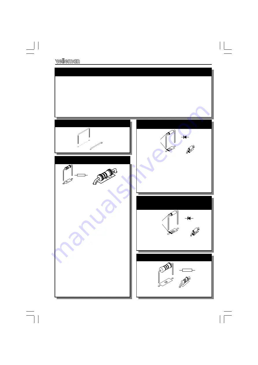
2. Resistors
(check the color code)
R...
q
J1
q
J2
1. Jumperwires
q
D1 : 1N4007
q
D2 : 1N4007
q
D3 : 1N4007
q
D4 : 1N4007
q
D5 : 1N4007
q
D6 : 1N4007
q
D7 : 1N4148
3. DIODES (Check the polarity)
CATHODE
D...
q
ZD1 : 4V3
q
ZD2 : 5V1
4. Zener diodes
(Check the polarity)
CATHODE
ZD...
q
L2 : 1µH (1-0-B)
5. Axial coil
L2


