LPTA410
2
VELLEMAN
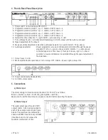
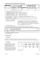
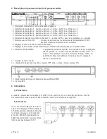
4. Front & Back Panel Description
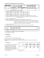
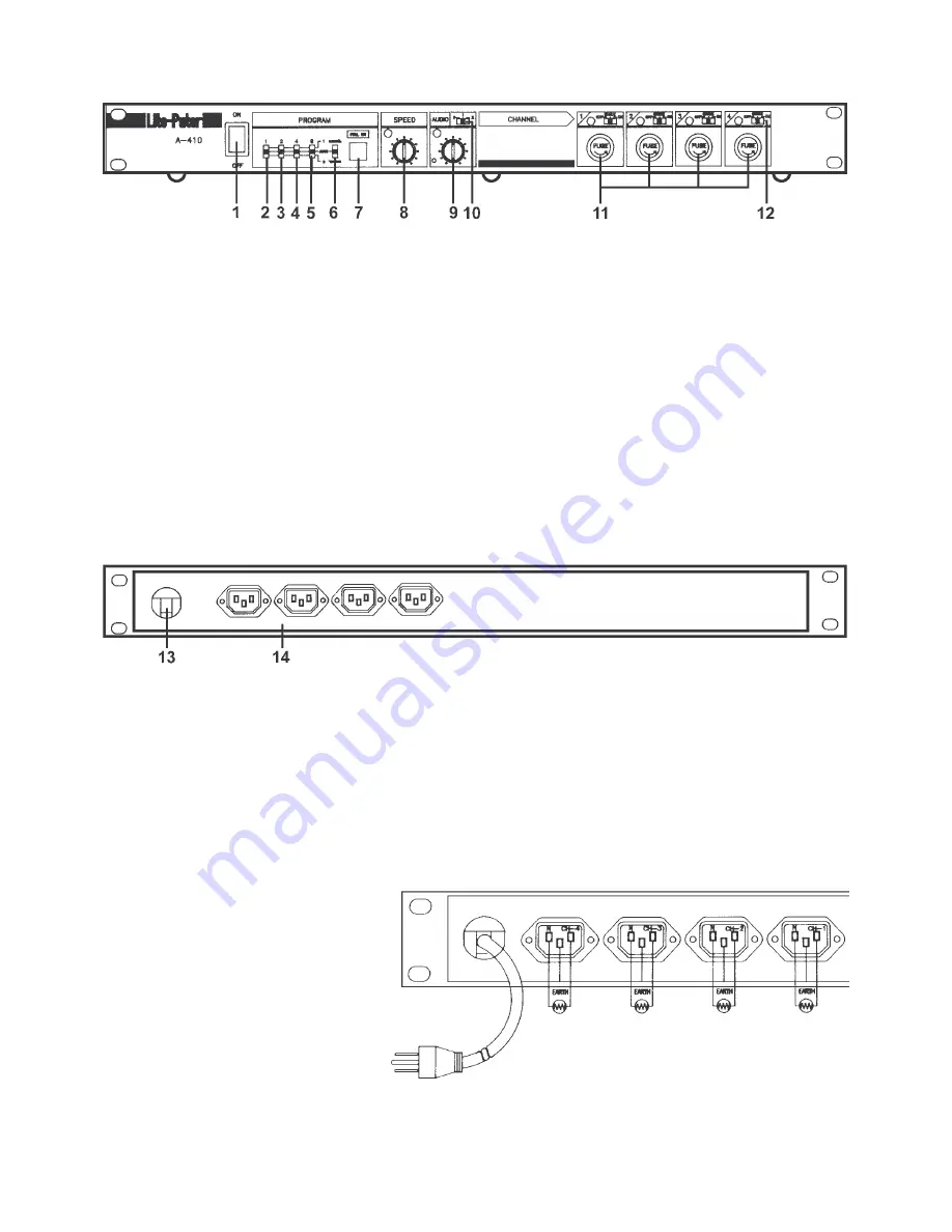
1. Power switch : turns the device ON or OFF.
2. Programme selection switch 1 : up = 1, middle = AUTO, down = 0
3. Programme selection switch 2 : up = 1, middle = AUTO, down = 0
4. Programme selection switch 4 : up = 1, middle = AUTO, down = 0
5. Programme selection switch 8 : up = 1, middle = AUTO, down = 0
6. Selector for chase direction : 1 = right, AUTO = auto-reversing, 0 = left.
7. FULL-ON push button : all 4 channels immediately go to 100% output until the button is released.
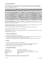
8. Speed adjustment for the chaser.
9. Music sensitivity adjustment (only when audio/speed selector is in audio mode (n°10 fig. above).
10. Audio/speed selector
: chaser programme is music-controlled and/or controlled through the speed
adjustment : left = 0 = speed = chase function, middle = 1 = audio = music-
controlled operation of the chaser (1 flash per 2 beats), right = 2 = chaser
operation is music-controlled and is controlled through the speed adjustment (1
flash per beat).
11. Output fuses : 4 x 4A.
12. Mode selection button per channel : left = always OFF, middle = chaser, right = always ON.
13. Power cord to mains 230Vac/50Hz.
14.
4 x EEC output sockets.
5. Connections
a) Mains Input
The colour coding for the wires inside the cable (3 x 1.5mm
2
) is as follows:
Brown = positive (L), blue = neutral (N), green/yellow = earth (E).
Make sure the earth connectors are properly connected before operating the device.
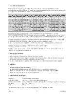
b) Mains Output
The signal output goes through 4 CEE
output sockets. A load can be applied to
each of these output sockets (see figure
below). The maximum load allowed per
channel is 920W (resistive load) or 460W
(inductive load). Do not surpass the
maximum total current of 16A !


