19
Switch the mains voltage switch to OFF, ie. fully down.
Connect the mains connector via a lead to a mains outlet. The plug may have to be changed for your
country. In that case, cut off the plug from the lead, and connect an appropriate plug for your country.
Connect the blue wire to the N connector of the mains, the brown wire to the L connector and the
yellow/green wire to the earth.
When connected to the mains, the red LED at the front should light up.
Switch the mains switch to ON ie. fully up. The LED at the front should flicker green/red while the
amplifier is warming up. After approx. one minute, the green LED will be continuously lit, you will also
hear a relay energise.
Check the following voltages with a volt meter:
Approx. 6.3 VAC on the terminals marked 6.3 VAC (SK3 and SK4) on each amplifier half. 6.3V should
also be found at connectors 2 and 7 of the tube sockets, V1 to V8.
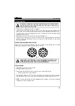
Fit the small tubes:
V9
and
V10
, type ECC83 or 12AX7, CV492.
V11
, type ECC82 or 12AU7, CV491.
Again connect the amplifier to the mains and set the mains switch to ON (fully up).
Wait until the green LED is lit continuously.
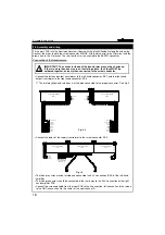
Now check the voltages on the PCB, measure the voltages with respect to earth. Earth can be taken
from lead
J26
(next to the mains switch). Measure the voltages at the points indicated on the PCB.
NOTE:
The measured voltages may differ depending on the tolerances of the mains connected.
Voltages of 0.4V cannot yet be checked.
29. Final inspection
Final inspection
ATTENTION: THERE ARE VOLTAGES OF MORE THAN 400V AT MANY POINTS
ON THE PCB. Ensure that suitable insulated measuring leads are used. Ensure
that no children are in the vicinity.
!
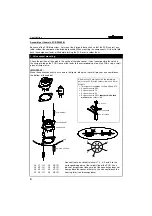
2
1
7
1
7
2
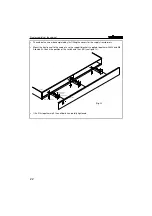
Fig. 11
FIRST SWITCH OFF THE MAINS VOLTAGE AND REMOVE THE MAINS CORD
FROM THE SOCKET. WAIT FOR A COUPLE OF MINUTES UNTIL THE HIGH
VOLTAGES ON THE SUPPLY ELCOS HAVE DISSAPEARED.
!

