16
To pass to the next or previous step, push the button shortly.
To go through the menu quickly, keep the button pressed.
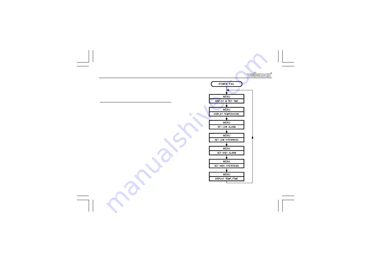
Sequence of the menus (see also fig. 8.0) :
1) TIME indication and setting
2) TEMPERATURE indication
3) LOW ALARM setting
4) LOW ALARM HYSTERESIS setting
5) HIGH ALARM setting
6) HIGH ALARM HYSTERESIS setting
7) ALTERNATELY TIME/TEMPERATURE indication
Pushing the button again causes the TIME to be redisplayed, etc... .
REMARK:
When going through the different alarm settings, at every single step
the corresponding LED is lit, where the relay belonging to the alarm
in question remains "OFF". So, the alarms will only react if the
controller is in menu 1, 2 or 7. As soon as one of the alarm values is
reached, the corresponding indication LED starts flashing and the
relay belonging to it is driven on.
Adjustment & usage
FIG. 8.0
Summary of Contents for K641LX
Page 20: ...20 7 0 SCHEMATIC DIAGRAM Schematic diagram...
Page 21: ...21 PCB 8 0 PCB...
Page 22: ...22 PCB...
Page 23: ...23 PCB PCB...


