5
Assembly hints
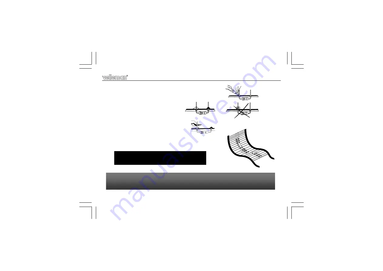
1.3 Soldering Hints :
1-
Mount the component against the PCB surface and carefully solder the leads
2-
Make sure the solder
joints are cone-shaped and shiny
3-
Trim excess leads as close as possible to the solder joint
REMOVE THEM FROM THE TAPE ONE AT A TIME !
AXIAL COMPONENTS ARE TAPED IN THE
CORRECT MOUNTING SEQUENCE !
You will find the colour code for the resistances and the LEDs in the HALG
(general manual) and on our website: http://www.velleman.be/common/service.aspx
Summary of Contents for K641LX
Page 20: ...20 7 0 SCHEMATIC DIAGRAM Schematic diagram...
Page 21: ...21 PCB 8 0 PCB...
Page 22: ...22 PCB...
Page 23: ...23 PCB PCB...


