H7200-ED2-24
Board1:
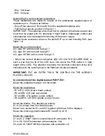
Mount the pins for connecting T4 to T6
Mount six Faston clamps for E B C (left and right)
Mount the 5W resistances R41 to R43 of 0.22 Ohm vertically and with the body
as on the PCB annotation. (see figure 3.2)
Board2:
Mount the pins for connecting T7 and T8 (T6 remains open)
Mount three Faston clamps for E B C next to R41/R44.
Mount the 5W resistances R44 and R45 for 0.22 Ohm vertically and with the
body as on the PCB annotation. (R43 remains open)
IMPORTANT:
PUT AN EXTRA THICK TIN COATING ON THE ALREADY
PLATED CIRCUITS
B) Construction of base PCB P7200B
ATTENTION: The additionally supplied piece of resistance wire of about 50 cm
is not to be used to construct jumpwires.
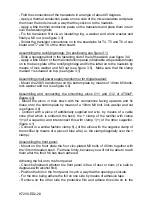
Mount the jumpwires marked with J
Mount the resistances:
- R1, 6K8 (blue, grey, red)
- R2, 8K2 (grey, red, red)
- R3 to R8, 4K7 (yellow, purple, red)
- R9 to R12, 220 Ohm (red, red, brown)
- R13 and R14, 2K2 (red, red, red)
- R15 and R16, 2K7 (red, purple, red)
- R17 and R18, 820 Ohm (grey, red, brown)
- R19 to R22, 22K (red, red, amber)
- R23 and R24, 1K2 (brown, red, red)
- R25, 100K (brown, black, yellow)
- R26, 15K (brown, green, amber)
- R27, 100 Ohm (brown, black, brown)
- R28, 1K (brown, black, red)
- R29, 330 Ohm (orange, orange, brown)
- R30, 220K (red, red, yellow)
- R31, 18 Ohm (brown, grey, black)
- R32, 270K (red, purple, yellow)
- R33, 12K (brown, red, amber)
- R34, 27K (red, purple, amber)
- R35, 39 Ohm (amber, white, black)
Mount the diodes: (pay attention to polarity!)
Summary of Contents for K7200
Page 2: ......
Page 3: ...INDEX GEBRUIKSAANWIJZING 4 MODE D EMPLOI 13 OPERATING INSTRUCTIONS 23 GEBRAUCHSANWEISUNG 32 ...
Page 42: ...H7200 ED2 42 ...
Page 43: ...H7200 ED2 43 ...
Page 44: ...H7200 ED2 44 ...
Page 45: ...H7200 ED2 45 ...
Page 46: ...H7200 ED2 46 ...
Page 47: ...H7200 ED2 47 ...
Page 48: ...H7200 ED2 48 ...
Page 49: ...H7200 ED2 49 ...
Page 50: ...H7200 ED2 50 ...
Page 51: ...H7200 ED2 51 ...
Page 52: ...H7200 ED2 52 ...
Page 53: ...H7200 ED2 53 ...
Page 54: ...H7200 ED2 54 ...


