background image

MUTE

STBY

THERMAL

S/C

SHUTDOWN

PROTECTION

+VS

7

BUFFER DRIVER

11

+PWVs

13

OUT

14

BOOT LOADER

12

CLIP DET

5

-PWVs

15

-VS

8

STBY-GND

1

STBY

9

MUTE

10

SGND

4

IN+

3

IN-

2

BOOTSTRAP

6

IC4

TDA7293V

R36

15K

R13

15K

R12

15K

R31

15K

R35

680R

R39

10R/1W

GP4/OSC2

3

Vdd

1

GP5/OSC1/CLKIN

2

GP3/MCLR/Vpp

4

GP2/T0CKl

5

GP0

7

GP1

6

Vss

8

IC1

PIC12C508A

5

6

7

IC2B

LM258

3

2

8

4

1

IC2A

LM258

1

2

6

4

IC3

MOC3041

T1

BC547

SW1

STBY / ON

SK1

INPUT

SK2

BYPASS

R7

15K

R4

1K

R3

15K

R21

1M

R23

1K

R32

100K

D2

1N4148

LD6

L-424YDT

C20

10µ

C19

10µ

C9

2n2

R33

100R

C13

2u2

RX

Rload

R1

1K

R8

15K

LD4

L-424YDT

LD5

L-424YDT

C28

47µ/63V

C14

2u2

C27

47µ/63V

R9

15K

C10

220nF

L1

8T 1.5mm dia 8mm

SK9

LS+

SK10

LS-

SK3

Mains in from 2A fuse + switch

SK4

Transfo Prim

TR1

TIC246M

R17

100R

R40

4.7R / 10W

C15

100NF/250VAC

C16

100NF/250VAC

R19

470R

R18

1K

C8

100n

C1

100n

R24

470K

R27

100K

C34

10.000uF/50V

C33

10.000uF/50V

C32

10.000uF/50V

C31

10.000uF/50V

C18

10µ

C17

10µ

ZD1

20V 1.3W

C25

47µ/63V

C26

47µ/63V

C7

100n

C6

100n

R30

0R

R34

0R

R10

15K

D3

1N4148

D4

1N4148

D5

1N4148

D6

1N4148

C3

100n

C4

100n

R22

470R

C29

220µ/63V

C30

220µ/63V

R20

2K2 / 0.6W

C2

100n

C5

100n

+5V

+5V

+5V

+5V

+5V

LD7

L-424YDT

R5

470R

+5V

Stby / ON

Stby / ON

Auto on

Clip detect

Auto on

CLIP LED

Clip detect

CLIP LED

+5V

OFF / Stby

ON

CLIP

Temp error

5mV input signal detector

DC Protection (fuse blow)

INTEGRATED MONO MOSFET AMPLIFIER

K8040

1.0

+5V

+35V

-35V

+35V

-35V

SK5

25VAC / 2A

SK6

25VAC / 2A

C23

D7

1N4148

R38

470R

R37

100K

R2

1K

R6

100R

LD8

L53MWC

T2

BC547

+5V

+5V

backlight

+

-

AC1

AC2

BR1

BRIDGE RS603

1

2

SK7

Temp sens.

1

2

SK8

Power meter

I

O

GND

VR1

UA7805

JGND

0R

R14

100R

R15

15K

C21

10µ

D1

1N4148

C24

10µ

R25

470K

R26

470K

SW2

SW KRS1243

R16

2K2 / 0.6W

+35V

DC prot. test

C12

1uF

C11

1uF

LD1

LED3RL

R11

470R

+5V

LD2

LED3RL

R28

2K2 / 0.6W

+35V

LD3

LED3RL

R29

2K2 / 0.6W

Power supply indication 

D8

1N4148

Values are for reference only


Summary of Contents for K8040

Page 1: ...solder points 299 Difficulty level beginner 1o 2o 3o 4o 5 advanced K8040 HIGH END mono mosfet power amplifier ILLUSTRATED ASSEMBLY MANUAL H8040IP 1 On Temp error Clip Auto power 8040 Mosfet Power Ampl...

Page 2: ...VELLEMAN COMPONENTS Legen Heirweg 33 9890 Gavere Belgium http www velleman be...

Page 3: ...gonal cutter to trim excess wires To avoid injury when cutting excess leads hold the lead so they cannot fly towards the eyes Needle nose pliers for bending leads or to hold compo nents in place Small...

Page 4: ...manual updates indicated as NOTE on a separate leaflet 1 3 Soldering Hints 1 Mount the component against the PCB sur face and carefully solder the leads 2 Make sure the solder joints are cone shaped a...

Page 5: ...Orange Orange Orange Orange Orange Orange Oranje 3 4 Giallo Amarelo Amarillo Keltainen Gul Gul Gul Gelb Yellow Jaune Geel 4 5 Verde Verde Verde Vihre Gr n Gr n Gr nn Gr n Green Vert Groen 5 6 Blu Azul...

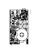
Page 6: ...described CONSTRUCTION q D1 1N4148 q D2 1N4148 q D3 1N4148 q D4 1N4148 q D5 1N4148 q D6 1N4148 q D7 1N4148 q D8 1N4148 2 Diodes check the polarity CATHODE D Construction q J1 q J2 q J3 q J4 q J5 q J6...

Page 7: ...0R 6 8 1 q R36 15K 1 5 3 q R37 100K 1 0 4 q R38 470R 4 7 1 q R39 10R 1W 1 0 0 q JGND 0R 0 If long input signal wires are used a low input impedance can be useful In this case mount for RX a 680R 6 8 1...

Page 8: ...are delivered with the kit if you bought two amplifi ers for stereo then one amplifier can be built with red connectors right amp and one with the black connec tors 10 RCA connectors Mount them straig...

Page 9: ...2 pole Transformer output F First slide these two connec tors in each other 12 Terminal blocks Construction Check that the position corresponds with the PCB silk printing q SK7 2 pole Temp sensor q S...

Page 10: ...Mount the coil and make sure to have a perfect soldering q L1 8 Turns dia 8mm 14 Coil L q VR1 UA7805 16 Voltage regulator The back side corresponds to the thick line q C17 10 F q C18 10 F q C19 10 F q...

Page 11: ...tion q BR1 RS603 18 Bridge rectifier Check the polarity q C31 10 000 F q C32 10 000 F q C33 10 000 F q C34 10 000 F 20 Power electrolytic capacitors Check the polarity C q IC1 VK8040 PIC12C508 q IC2 C...

Page 12: ...is a white LED serving as backlight for the power meter q LD8 L5WD 5mm white 22 Mounting front LED s Check the polarity Short lead Cathode or Construction 7mm C 12mm IMPORTANT Mount these LED s exact...

Page 13: ...ION The bolt should be inserted on the side of the IC holder with the countersunk opening B DO NOT TIGHTEN THE NUT YET 1 Position the IC onto the PCB 2 Make sure that the support plate is touching the...

Page 14: ...e wires For 230V 220V to 240V edge orange then brown and black For 115V 110V to 120V edge brown then orange and black Using a black marker erase the not used voltage on the rear panel of the unit Seco...

Page 15: ...feet on the aluminum profile using two M4 hexagonal Al len screws Use the supplied Allen wrench It is advisable to stick the protection adhe sive onto the feet q Cut the thread in the front and back...

Page 16: ...int from the aluminum fixation from the hole closest to the back end This fixation will be used later to connect the ground and earth q Mount the three 5mm 0 14 spacers as shown in the drawing Use thr...

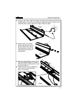
Page 17: ...o M3 nuts and two hexagonal bolts into the pro file the nuts will be used for the temperature sensor the bolts will be used for the IC support plate q Mount the temperature sensor check the exact posi...

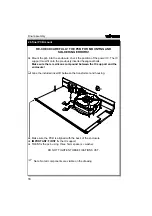
Page 18: ...al bolts Make sure there is silicone compound between the IC support and the enclosure q Glue the included insert C between the transformer and housing q Make sure the PCB is aligned with the back of...

Page 19: ...al Brown for Live Yellow green for earth Use 3 pieces of about 10cm for later connection to the PCB mains connector q Mount the speaker connectors onto the rear panel black negative FTake care of the...

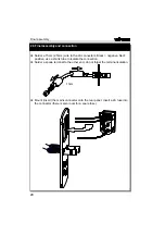
Page 20: ...tube to isolate the connection q Solder a spade terminal to the other end do not forget the terminal isolation q Mount insert the mains connector onto the rear panel Insert a 2A fuse into the connect...

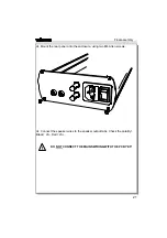
Page 21: ...he rear panel onto the enclosure using two M4 Allen screws q Connect the speaker wires to the speaker output tabs Check the polatity Black LS Red LS DO NOT CONNECT THE MAINS WIRING WITH THE PCB YET Fi...

Page 22: ...er is positioned straight q Connect the meter to the PCB SK8 q Mount the front panel onto the front using two M4 Allen screws FCheck the position of the LED s and check if the button is working correc...

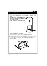
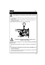
Page 23: ...q Connect a 60W light bulb in series with the Live Brown wire and the Live connection on the PCB q Mount both the fuse and the spare fuse in the fuse holder CAUTION Some points on the PCB are connecte...

Page 24: ...sed live parts Disconnect the mains plug Now the brown Live wire can be connected directly to the connector AK3 F Check the user manual to test all functions and operation of the unit Finally the cove...

Page 25: ...25 DIAGRAMS...

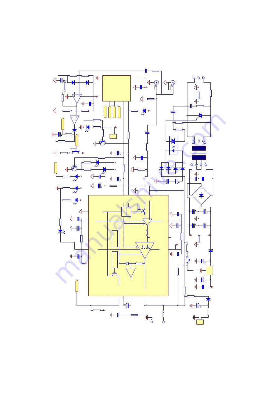
Page 26: ...100n R24 470K R27 100K C34 10 000uF 50V C33 10 000uF 50V C32 10 000uF 50V C31 10 000uF 50V C18 10 C17 10 ZD1 20V 1 3W C25 47 63V C26 47 63V C7 100n C6 100n R30 0R R34 0R R10 15K D3 1N4148 D4 1N4148 D5...

Page 27: ...Velleman Kit...

Page 28: ...VELLEMAN Components Legen Heirweg 33 9890 Gavere Belgium Europe Info http www velleman be Modifications and typographical errors reserved Velleman H8040IP 2001 ED1...

Reviews: