


10
Assembly
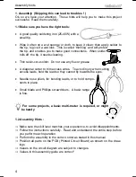
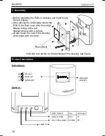
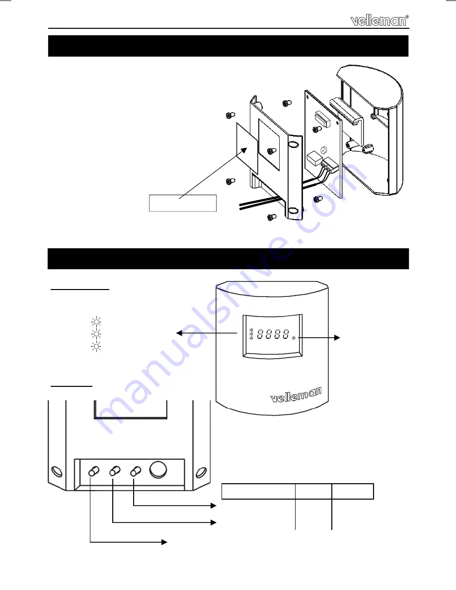
3. Assembly
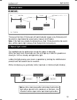
select mode
Light / Buzzer
sleep / snooze
dim / cancel alarm
run mode
on
off
time
hour
minutes
time set
alarm set
light/buzzer
alarm/light
activated
Indications :
Control :
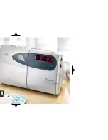
Product description
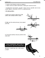
Stick the rear sticker on the backside of the housing, see figure.
Rear-sticker
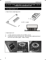
Before mounting the PCB on its place you must mount
the red display.
After placing the red display mount the
PCB in the front cover with the 4-digit
display facing to the red
display window with 4 screws.
At last mount the rear of the housing
and closed with 4 screws.
(a)
(b)
(c)