background image

Features & specifications 


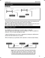
The K8091 is an attractive LED clock with connection possibility for a nightlight. 
15 minutes before the set time, the light intensity of the connected light will 
increase up to full power at set time and beeps will be heard. The beep length is 
gradually built up so you will not be startled by a sudden alarm signal. 


Features :




clock with red 7-segment display. 



possibility to connect any lamp armature fitted with an incandescent light bulb 



sleep function (15 min) for slow light power-off. 



snooze function with alarm repeat function after 8 min. 



manually settable light intensity. 



beep and / or light option. 


Specifications




power supply: 220- 240V AC / 50Hz. 



lamp power: 40 ~ 100W max. 



power consumption: < 1W (without lamp) 



dimensions: 92x45x101mm / 3.6x1.8x3.9" 
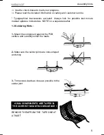
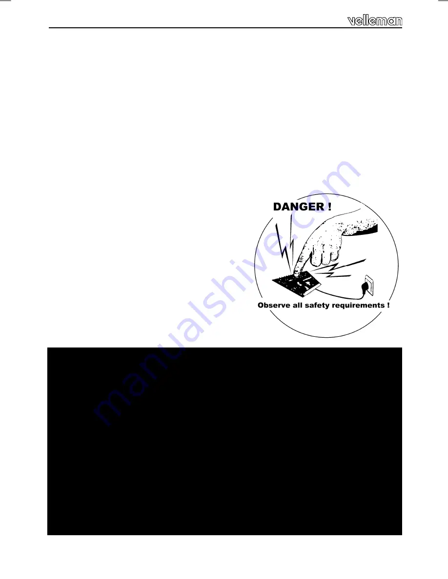
WARNING ! 

 
ALL PARTS IN THIS KIT CARRY HAZARDOUS VOLTAGES  WHICH CAN KILL ! 
 
Do not touch any part of the kit  while connected to the AC grid. 
Do not modify the kit in any way. 
Do not use the kit if the enclosure is damaged or open. 
 
For use with regular incandescent lightbulbs (40-100W) only. 
 
Not suited for low-voltage halogen lighting, energy saving bulbs, led lighting, 
fluorescent lighting, motors, buzzers, transformers etc... 
 
We highly recommend to have your kit inspected by a qualified technician  
before connecting it to the AC power for the first time or after a malfunction. 

Summary of Contents for K8091EU

Page 1: ...LED CLOCK with SLOW ON DIMMER H8091IP 1 Attractive LED clock with nightlight connection K8091EU K8091EU...

Page 2: ......

Page 3: ...in manually settable light intensity beep and or light option Specifications power supply 220 240V AC 50Hz lamp power 40 100W max power consumption 1W without lamp dimensions 92x45x101mm 3 6x1 8x3 9 W...

Page 4: ...gonal cutter to trim excess wires To avoid injury when cutting excess leads hold the lead so they cannot fly towards the eyes Needle nose pliers for bending leads or to hold compo nents in place Small...

Page 5: ...manual updates indicated as NOTE on a separate leaflet 1 3 Soldering Hints 1 Mount the component against the PCB surface and carefully solder the leads 2 Make sure the solder joints are cone shaped a...

Page 6: ...0 1 B R13 10K 1 0 3 B R14 10K 1 0 3 B R16 10 1 0 0 B 1 2W metal film R8 47 4 7 0 B 9 R9 10 1 0 0 B 9 R10 470K 4 7 4 B 9 R11 470K 4 7 4 B 9 R12 100K 1 0 4 B 9 1 4W R15 220 2 2 1 B 1 Resistors R D1 1N41...

Page 7: ...blocks 10 1W Resistor VR2 UA78L05 9 Voltage regulator VR C8 220 F C9 10 F 11 Electrolytic capacitors Watch the polarity C C6 100nF C7 470nF 13 Capacitors SW1 SW2 SW3 14 Push buttons TR1 BT136 15 Triac...

Page 8: ...e rubber foot and stick it to the PCB as shown 2 Position the coil onto the rubber foot Bend the leads carefully and insert them into their soldering pads Solder carefully 1 Four digit display coil 2...

Page 9: ...male and female cable Connect the female cable connector to the output connector SK2 the male cable connector to output connector SK1 When both cables have been connected to the K8091EU mount the str...

Page 10: ...Control Product description Stick the rear sticker on the backside of the housing see figure Rear sticker Before mounting the PCB on its place you must mount the red display After placing the red disp...

Page 11: ...ht buzzer deactivated Note From the moment that the alarm time is changed will this time be the default setting alarm time 5 First power up 6 Setting time alarm alarm functions Time setting First pres...

Page 12: ...he time setting you must press twice the select button to enter the alarm mode The alarm set indicator blinks to confirm you re in the alarm mode Press the middle button to set the minutes the right b...

Page 13: ...omatically repeat every 8minutes until the alarm is deactivated by pressing the manual on off button Note if the light was already illuminated more than 15minutes before the alarm time will the alarm...

Page 14: ...14 PCB 9 PCB...

Page 15: ...15 10 Schematic diagram Schematic diagram...

Page 16: ...Modifications and typographical errors reserved Velleman nv H8091IP 1 2014 rev 2 5 4 1 0 3 2 9 4 0 9 2 3 4 VELLEMAN NV Legen Heirweg 33 B 9890 GAVERE Belgium Europe...

Reviews: