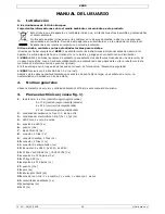
KSR5
V. 02 – 09/02/2018
3
©Velleman nv
4.
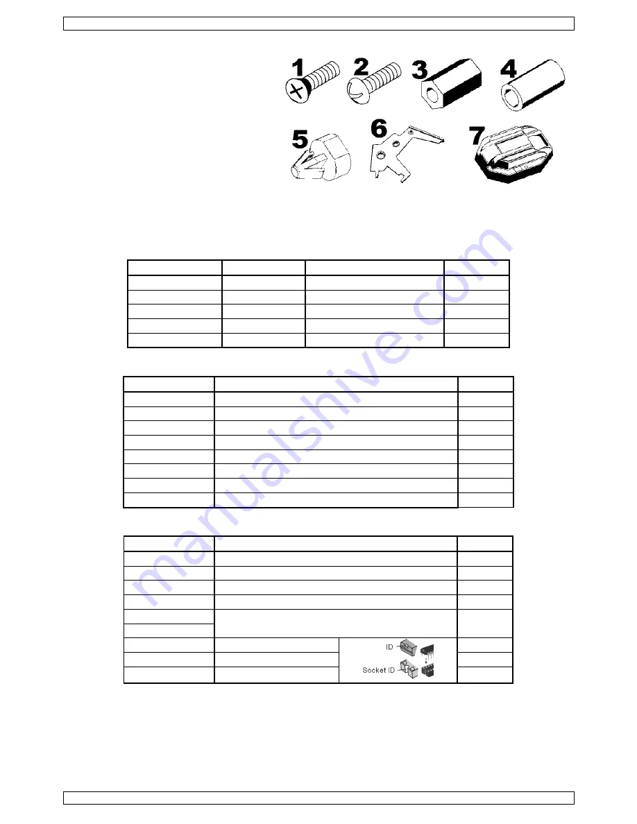
Mechanical Parts List
1.
2x screw 3x6mm (P13)
2.
10x screw 3x6mm (P14)
3.
hex post: 4x 10mm H (P15), 2x 12mm H
(P16)
4.
2x round spacer 10mm H (P17)
5.
2x PCB spacer (P18)
6.
2x antenna (P19)
7.
1x body (P20)
5.
Assembly
5.1
PCB Assembly
Start the assembly by mounting the jumper wires and resistors. The components codes are printed on the PCB:
Part ID
Description
Colour Code
Quantity
J1~16
jumper wire
n.a.
16
R16~19
10
brown/black/black/gold
4
R1/4~7/12~15
10K
brown/black/orange/gold
9
R8~11
22K
red/red/orange/gold
4
R2/3
1M
brown/black/green/gold
2
Mount the capacitors, transistors and diodes next:
Part ID
Description
Quant.
C7
ceramic capacitor 103
1
C1~6
ceramic capacitor 104
6
EC1~3
electrolytic capacitor 0.47µf
3
EC4
electrolytic capacitor 10µf
1
Q5~8
transistor C945
4
Q9~12
transistor 8050
4
Q1~4
transistor 8550
4
D1~4/7/8
diode 1N4004
6
Mount the IC sockets, the battery connector, the slide switch, the pins and the ICs.
Part ID
Description
Quant.
IC1
8 pins IC socket (fig.1 #16)
1
IC2~6
16 pins IC socket (fig.1 #14)
5
BAT.
battery connector (fig.1 #11)
1
SW.
slide switch (fig.1 #21)
1
M1 (+/-)
pins (fig.1 #18)
4
M2 (+/-)
IC1
555 (8 pins)
1
IC2/3
74LS109AP (16 pins)
2
IC4~6
74HC157AP (16 pins)
3
Fig. 2


