background image

PS5005


VELLEMAN 

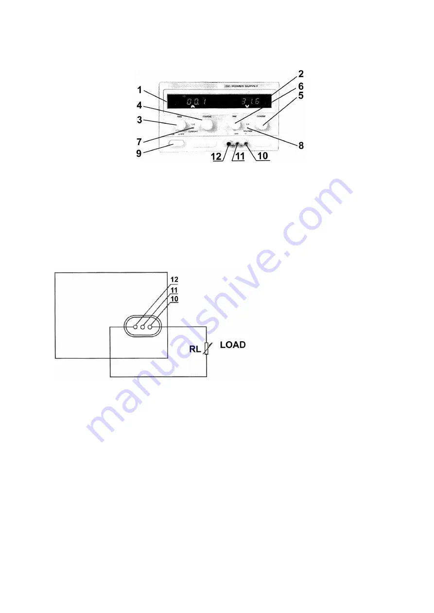
(10)  Output terminal (+): used for the connection of the load's positive terminal. 
(11)  Ground connection of the housing: the housing is grounded. 
(12)  Output terminal (-): used for the connection of the load's negative terminal. 


3.2.  Operating Procedure 


1)  Using the device as a C.V. source 

 
Turn adjustments (3) and (4) to the extreme right prior to activating the device. Activate the device. Use adjustment 
(5) to obtain a voltage that is close to the desired value. Consequently, you should use fine-tuning adjustment (6) to 
install the exact value. The C.V. indicator comes on. 
 

2)  Connecting the Load 


The load is connected as shown in the figure above. You can read the output current (1) and the output voltage (2) 
from the display as soon as the device has been switched on. The C.V. indicator (8) is lit if the device is in the C.V.-
mode. The C.V. LED is off and the C.C. LED will light if the Amp display indicates a value that exceeds the installed 
value. When this happens, the device will automatically go into the current-limiting mode. Install a load that will allow 
the device to function normally. 
 

3)  Using the device as a C.C. source 

 
Use the power switch (9) to activate the device. Turn adjustments (5) and (6) to the extreme right and turn 
adjustments (3) and (4) to the extreme left. Connect the load. Adjust (3) and (4) until the desired current is obtained. 
The C.C. indicator is now lit while the C.V. indicator is off. 
 

4)  Use of the current-limiting adjustment in the C.V.-mode 

 
Place both of the current adjustments, viz. (3) and (4), in the max. position. You can now set the current-limiting point 
arbitrarily (max. ± 5.5A). Proceed as follows : activate the device, connect a variable load and adjust the load so that 
the current matches the desired current-limiting point. Meanwhile, you should also manipulate current-adjustments 
(3) and (4) until the C.C. LED lights. The value on the Amp display is identical to the current-limiting point. 


Summary of Contents for PS5005

Page 1: ... output current and output voltage are indicated through LED displays 2 Technical Specifications Input Voltage 220V 10 50Hz 2Hz Output Voltage 0 50V Output Current 0 5A Source Regulation C V 1 x 10 4 1mV C C 2 x 10 3 1mA Load Regulation C V 1 x 10 4 5mV C C 2 x 10 3 5mA Ripple C V 1 0mVrms Protection current limiting and short circuit protection Indication Accuracy a Volt indication LED 1 2 digits...

Page 2: ...he C C LED will light if the Amp display indicates a value that exceeds the installed value When this happens the device will automatically go into the current limiting mode Install a load that will allow the device to function normally 3 Using the device as a C C source Use the power switch 9 to activate the device Turn adjustments 5 and 6 to the extreme right and turn adjustments 3 and 4 to the ...

Page 3: ...afe operation of the device 5 Accessories 1 user manual 1 power cable 6 Schematics See figure on page 12 The information in this manual is subject to change without prior notice PS5005 DC GESTUURDE VOEDING 1 Inleiding Aan alle ingezetenen van de Europese Unie Belangrijke milieu informatie betreffende dit product Dit symbool op het toestel of de verpakking geeft aan dat als het na zijn levenscyclus...

Page 4: ...aaiknop om de uitgangsspanning bij benadering in te stellen 6 C V fijnregeling draaiknop om de uitgangsspanning precies in te stellen 7 C C indicator deze LED gaat branden wanneer het toestel zich in de constante stroom mode bevindt 8 C V indicator deze LED gaat branden wanneer het toestel zich in de constante spannings mode bevindt 9 Voedingsschakelaar drukknop die wordt gebruikt om het toestel i...

Page 5: ... stroombegrenzingspunt Regel ondertussen ook de stroomregelingen 3 en 4 bij tot de C C LED gaat branden De waarde op de Amp display is identiek aan het stroombegrenzingspunt 4 Veiligheidsvoorschriften De PS5005 is optimaal beveiligd dankzij de beveiliging tegen kortsluiting en het stroombegrenzingspunt Let wel het vermogensverlies van de transistors is maximaal bij kortsluiting U moet het toestel ...

Page 6: ... pilotage CC à haute précision équipée d une sortie réglable Vous pouvez utiliser cette sortie pour une tension constante C V ou un courant constant C C La tension de sortie peut être réglée arbitrairement de 0V à 50V lorsque l appareil se trouve dans le mode de tension constante mode C V Le point de limitation de courant max 5 5A est également instaurable dans ce mode Le courant de sortie peut êt...

Page 7: ...de la sortie connectez la borne de connexion positive de la charge 11 Connexion de terre du boîtier le boîtier est mis à la terre 12 Borne de connexion négative de la sortie connectez la borne de connexion négative de la charge 3 2 Instructions d opération 1 La PS5005 comme source de tension constante C V Tournez les réglages 3 et 4 à l extrême droite avant de brancher l appareil Branchez l appare...

Page 8: ...eil La PS5005 est une source de courant importante n oubliez pas de prendre toutes les précautions nécessaires L appareil doit être bien ventilé pour éviter les surchauffes lors d un emploi à puissance maximale Tenez compte du risque de brûlures évitez de toucher la surface du dissipateur des doigts lorsque vous employez l appareil à pleine puissance Un emploi défendu de l appareil et une températ...

Page 9: ...e a Volt Anzeige LED 1 2 stellig b Amp Anzeige LED 2 2 stellig Betriebstemperatur 0 bis 40 C RH 90 Abmessungen 305mm x 265mm x 160mm Autonomie 8 Std ständiger Betrieb bei max Belastung 3 Beschreibung 3 2 Bedienelemente und Beschreibung der Frontplatte 1 Amp Display LED zeigt den Ausgangsstrom an 2 Volt Display LED zeigt die Ausgangsspannung an 3 C C Feinabstimmung Drehschalter zur Feinabstimmung d...

Page 10: ...r 5 und 6 völlig nach rechts und drehen Sie die Schalter 3 und 4 völlig nach links Schließen Sie die Last an Regeln Sie 3 und 4 bis der gewünschten Stromwert bekommen wird Die Anzeige brennt während die C V Anzeige angeschlossen ist 4 Anwendung der Strombegrenzungsfunktion im C V Modus Stellen Sie die zwei Stromregler 3 und 4 in die maximale Position Sie können jetzt den Strombegrenzungspunkt will...

Page 11: ...berhöhte Umgebungstemperatur können zu einer Fehlfunktion mancher internen Komponenten führen Wenn das passiert ist es möglich dass die Ausgangsspannung die Nennausgangsspannung überschreitet SEIEN SIE VORSICHTIG BEI DER ANWENDUNG DIESES GERÄTES UND VERMEIDEN SIE UNNÖTIGE BESCHÄDIGUNG DER LAST Der 3 polige Erdungsanschluss des Stromkabels muss sicher geerdet sein um einen sicheren Betrieb des Gerä...

Page 12: ...PS5005 VELLEMAN 12 SCHEMATICS SCHEMA ...

Reviews: