


SPBS4
VELLEMAN
1
SPBS4 - REVERSING RADAR WITH LCD DISPLAY
1. Introduction
To all residents of the European Union
Important environmental information about this product
This symbol on the device or the package indicates that disposal of the device after its lifecycle could harm
the environment.
Do not dispose of the unit (or batteries) as unsorted municipal waste; it should be taken to a specialised
company for recycling.
This device should be returned to your distributor or to a local recycling service.
Respect the local environmental rules.
If in doubt, contact your local waste disposal authorities.
Thank you for buying the
SPBS4
! The
SPBS4
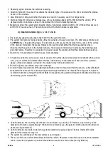
reversing radar uses the principle of distance measurement and fuzzy
logic. As the vehicle is slowing backing up, the ultrasonic system detects obstacles located behind the vehicle and
warns the driver via clear audio and/or visual signals, who is then able to avoid the obstacles.
2. Features
1. Wide detecting range with a limited blind area
2. High stability and reliability without false alarm
3. Easy installation
4. Operates under extreme weather conditions (e.g. heavy rain, snow, strong wind, extreme temperatures)
3. Specifications
Operating voltage
DC 10-28V
Rated voltage
DC 12V
Operating current
150mA
Displaying distance
0.22~2.5m
Blind area
< 22cm
Sensor frequency
40kHz±1kHz
Warning modes
sound, distance & direction
Display
LCD
Operating temperature
-30 to +70°C
Storage temperature
-35 to +85°C
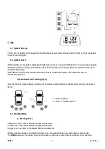
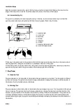
4. Description
(fig. 1)
1.
Detection unit: composed of 2 – 4 ultrasonic sensors
2.
Control unit: microprocessor-controlled, uses a signal processing circuit
3.
Warning unit: LCD display. When the car reverses, this unit warns the driver of obstacles via audio +
display of direction of and distance to the obstacle.


