background image

VDP150SC4 v2 

VELLEMAN 

-  When handling a halogen lamp, do not touch it with your bare hands. Use a cloth to insert or remove it. 
-  Do not install lamps with a higher wattage than that for which the device was designed, as they generate higher 

temperatures and may damage the unit. 

-  Use a 15V/150W GZ6.35 lamp (order code 

LAMP150/15

). 

-  Procedure:  1.  Unscrew the screws on the bottom of the housing and open the lid. 
 

2.  Remove the old lamp if applicable, and insert the new one. 


3.  Close the lid and fix the screws. 


Remark: Do not operate the device with an open lid. 


b) The Fuse


-  Disconnect the unit from the mains to fit or replace the fuse. 
-  If the lamp burns out, chances are you will need to replace the fuse on the rear panel of the base as well. 
-  Replace a blown fuse with a fuse of the same type and rating (see 

7. Technical Specifications

, page 4) : 

1.  Pull out the fuse holder at the rear panel. 
2.  Remove the old fuse and install a new one. 
3.  Replace the fuse holder. 


c) The Device


-  A qualified person should install this device respecting EN 60598-2-17 and all other applicable norms.. 
-  The construction to which the device is attached should be able to support 10 times the weight for one hour 

without deformation. 

-  The installation must always be secured with a secondary attachment e.g. a safety cable. 
-  Never stand directly below the device when it is being mounted, removed or serviced. Have a qualified 

technician check the device before you bring it into service. Have a qualified technician check the entire 
installation once a year. 

-  Install the device in a location where few people pass by and that is unreachable for unauthorised persons. 
-  Overhead mounting requires extensive experience : calculating work load limits, determining the installation 

material to be used… Have the material and the device itself checked regularly. Do not attempt to install the 
device yourself if you lack these qualifications as improper installation may result in injuries. 

-  Make sure there is no flammable material within a 50cm radius of the device. 
-  A qualified electrician should carry out the electric connection. 
-  Connect the device to the mains with the power plug. Install a switch with a minimum distance of 3mm between 

contacts if the device is to be connected directly with the mains. In general, lighting effects should not be 
connected to dimming packs. 

-  The installation has to be approved by an expert before the device is taken into service. 


5. Operating Instructions 


a)  DMX control 

 
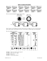
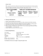
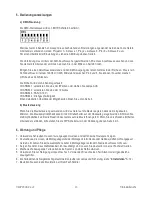
The DMX start address of the controller is defined by the 9 DIP switches.  


Since this device has 4 channels, the following settings should be applied when chaining them together: projector 
1 = address 1, proj. 2 = address 5, proj. 3 = address 9 etc. 

Summary of Contents for VDP150SC4

Page 1: ...r smell will gradually disappear Never touch the device during operation as the housing heats up and contact may cause burns Note that damage caused by user modifications to the device is not covered...

Page 2: ...dary attachment e g a safety cable Never stand directly below the device when it is being mounted removed or serviced Have a qualified technician check the device before you bring it into service Have...

Page 3: ...last device in the DMX chain This is an XLR connector with a 120ohm 1 4W resistor between pin 2 and 3 You can make this yourself using a male XLR connector The unit is controlled by 4 channels CHANNEL...

Page 4: ...vice installed by a qualified technician 4 The moving parts must show no traces of wear and tear and should be well balanced 5 Wipe the device clean regularly using a moist and clean cloth Do not use...

Page 5: ...king is de behuizing warmt op en contact kan brandwonden veroorzaken Schade veroorzaakt door wijzigingen die de gebruiker heeft aangebracht aan het toestel vallen niet onder de garantie Houd dit toest...

Page 6: ...ook vast met een veiligheidskabel Sta nooit recht onder het toestel wanneer u het plaatst verwijdert of schoonveegt Laat het toestel controleren door een geschoolde technicus voor u het in gebruik nee...

Page 7: ...e figuur bovenaan pagina 4 6 Reiniging en onderhoud 1 Alle gebruikte schroeven moeten goed zijn aangespannen en mogen geen sporen van roest vertonen 2 Er mag geen vervorming optreden van de behuizing...

Page 8: ...er des br lures Les dommages occasionn s par des modifications l appareil du c t du client ne tombent pas sous la garantie Tenez l appareil hors de port e d enfants et de personnes non qualifi s 3 Dir...

Page 9: ...l appareil pour l enlever ou lors du montage ou nettoyage Un technicien qualifi doit r viser l appareil avant la mise en service Organisez une r vision une fois par an Installez l appareil hors de po...

Page 10: ...ha ner plusieurs appareils mettez les interrupteurs DIP comme indiqu dans la figure en haut de la page 4 6 Nettoyage et entretien 1 Serrez les crous et les vis et v rifiez qu elles ne sont pas rouill...

Page 11: ...n k nnen Beim ersten Gebrauch k nnte es Rauch oder einen spezifischen Geruch geben Das ist normal und wird nach einiger Zeit allm hlich verschwinden W hrend des Betriebs nie das Geh use anfassen denn...

Page 12: ...euen 3 Bringen Sie die Sicherungsdose wieder in das Geh use ein c Das Ger t Lassen Sie das Ger t von einem Fachmann und gem den EN 60598 2 17 und allen anderen zutreffenden Normen installieren Die Kon...

Page 13: ...iten finden Sie unten Seite 3 b Musiksteuerung Wenn Sie die Musiksteuerung verwenden wird das Ger t auf die Musik reagieren dank dem eingebauten Mikrofon Die Musikempfindlichkeit kann mit dem Drehscha...

Page 14: ...30V AC 50Hz Stromverbrauch maximal 170W Sicherung F 2A 250V AC 5x20mm Artikelnummer FF2 Abmessungen 460 x 220 x 110mm Gesamtgewicht 9 4kg Lampe 1 x 15V 150W GZ6 35 Fassung LAMP150 15 Max Umgebungstemp...

Reviews: