background image


VTSSC78 

V. 01 – 12/04/2016 

©Velleman nv 

8.


Operating Temperature 

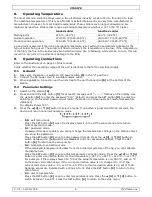
The most common soldering alloys used in the electronics industry consist of 60 % tin and 40 % lead. 
The operating temperature of this type of solder is detailed below and can vary from manufacturer to 
manufacturer. However, to meet RoHS requirements, these solders are no longer allowed and are 
replaced by lead-free solders that require a working temperature which is ± 30 °C (54 °F) higher. 


leaded solder 

lead-free solder 

Melting point 

215 °C (419 °F) 

220 °C (428 °F) 

Normal operation 

270-320 °C (518-608 °F) 

300-360 °C (572-680 °F) 

Production line operation 

320-380 °C (608-716 °F) 

360-410 °C (680-770 °F) 


A good joint is assured if the iron's operating temperature is set within the parameters suitable for the 
type of solder being used. The solder will flow too slowly if the temperature is too low; if the temperature 
is too high, the flux in the solder may burn which will give rise to billowing white smoke. In turn, this will 
result in a dry joint or in permanent damage to the PCB. 

9.


Operating Instructions 

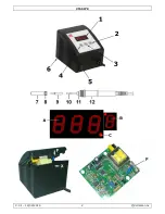
Refer to the illustrations on page 2 of this manual. 
Verify whether the operating voltage of the unit is identical to that of the electrical supply.  

9.1


General 

1.


Make sure the station is switched off (power switch 

[5]

 in the “0” position). 

2.


Connect the AC power cord to a suitable mains outlet. 

3.


When applicable, connect an earth wrist strap to the earth connection 

[6]

 at the bottom of the 

station. 

9.2


Parameter Settings 

1.


Switch on the station 

[5]

2.


Press and hold the SET button 

[2]

 for at least 5 seconds until “— — —” flashes on the display. Use 

the 

 button 

[4]

 to enter the password “010” (default) and press the SET button 

[2]

 to enter the 

setup menu. An incorrect password will return the station to normal operation mode (temperature 
indication). 
The display shows “F-0”.  

3.


Press the 


[4]

 or 


[3]

 button to select a mode. If no button is pressed within 15 seconds, the 

device will return to normal operation mode.  


o


F-0

: exit menu mode 

Press the SET button 

[2]

 when the display shows F-0 to exit the setup menu and return to 

normal operation mode. 

o


F-1

: password mode 

If password mode is enabled, you cannot change the temperature settings on the station unless 
you know the password. 
Press the SET button 

[2]

 once to enter password mode. Press the 


[4]

 or 


[3]

 button to 

switch between 000 (password mode disabled) and 100 (password enabled). Press the SET 
button 

[2]

 to return to the setup menu. 

o


F-2

: temperature correction mode 

If the displayed temperature deviates from the actual temperature of the tip, you can calibrate 
the display here. 
Press the SET button 

[2]

 once to enter temperature correction mode. Press the 


[4]

 or 


[3]


button to enter a correction factor for the temperature (–99 °C ~ +99 °C; –210 °F ~ +210 °F). 
For example, if the display shows 300 °C but the actual temperature is only 290 °C, add 10 °C 
to the shown correction value. If the current correction value is 00, change it to 10. If the 
current correction value is –20, set it to –10. If the current correction value is 20, set it to 30. 
Negative values are indicated with a minus in front. Press the SET button 

[2]

 to return to the 

setup menu. 

o


F-3

: unit of temperature 

Press the SET button 

[2]

 once to enter temperature mode. Press the 


[4]

 or 


[3]

 button to 

switch between °C and °F. Press the SET button 

[2]

 to return to the setup menu. 

Summary of Contents for VTSSC78

Page 1: ...DE SOUDAGE 80 W 230 V ESTACIÓN DE SOLDADURA 80 W 230 V LÖTSTATION 80 W 230 V STACJA LUTOWNICZA 80 W 230 V ESTAÇÃO DE SOLDADURA 80 W 230 V USER MANUAL 3 HANDLEIDING 9 MODE D EMPLOI 15 MANUAL DEL USUARIO 21 BEDIENUNGSANLEITUNG 27 INSTRUKCJA OBSŁUGI 33 MANUAL DO UTILIZADOR 39 ...

Page 2: ...VTSSC78 V 01 12 04 2016 2 Velleman nv ...

Page 3: ...cause serious burns tips and hot air away from the body clothes or other flammabl the hot air gun at the eyes Use gloves and or heat resistant tools to pick up the PCB assembly to prevent burns Always return the irons and gun to uses always let the device cool down after use and before stor Place the device on a level stable and fire resistant working surface Do not inhale solder fumes The vapours...

Page 4: ... nor its dealers can be held responsible for any damage extraordinary incidental or indirect of any nature financial physical arising from the possession use or failure of this product 4 How to Solder File off any dirt rust or paint on the parts you wish to solder Heat the parts with the soldering iron Apply resin based solder to the part and melt it with the soldering iron NOTE Be sure to apply a...

Page 5: ...hobbyist maintenance personnel and production staff alike The electronic circuitry enables you to set soldering temperatures between 150 and 480 C 302 to 896 F without replacing the tip The temperature is maintained to within 5 C 9 F of the normal operating temperature Heater fail detection If the heater circuit fails the display shows H E and heater power is cut Temperature lock features The temp...

Page 6: ...st 5 seconds until flashes on the display Use the button 4 to enter the password 010 default and press the SET button 2 to enter the setup menu An incorrect password will return the station to normal operation mode temperature indication The display shows F 0 3 Press the 4 or 3 button to select a mode If no button is pressed within 15 seconds the device will return to normal operation mode o F 0 e...

Page 7: ...ation may be cleaned with a damp cloth using small amounts of liquid detergent Never submerse the unit in liquid or allow any liquid to enter the case of the station Never use any solvent to clean the case If the iron or station should become faulty or for some reason does not operate normally the system should be returned to the service department of your authorized dealer or service agent 10 2 T...

Page 8: ...he same type and rating 4 Close the top cover and put the screw X back 11 Technical Specifications max heater power for soldering iron 80 W temperature range 150 480 C 302 896 F iron voltage 220 240 V weight 770 g dimensions 105 x 90 x 85 mm Use this device with original accessories only Velleman nv cannot be held responsible in the event of damage or injury resulting from incorrect use of this de...

Page 9: ...Raak de schacht soldeerpunt enz nooit aan dit kan ernstige brandwonden veroorzaken Houd de soldeerpunt en warme lucht uit de buurt van het of ander brandbaar materiaal Richt het toestel nooit op de ogen Draag handschoenen en of gebruik hittebestendig gereedschap om brandwonden te voorkomen Plaats de soldeerbout altijd terug in de houder bij een soldeerpauze Laat het toe afkoelen na gebruik en alvo...

Page 10: ...oldeerbout OPMERKING Breng eerst een beetje soldeerpasta aan op de component als u soldeer zonder harskern gebruikt Wacht tot het soldeer verhardt alvorens de onderdelen te bewegen OPGELET Wees voorzichtig bij het hanteren van een ingeschakelde soldeerbout om ernstige brandwonden te vermijden Bij het eerste gebruik kan de soldeerbout lichtjes roken te wijten aan een uitgedroogd verwarmingselement ...

Page 11: ...ardingsaansluiting 12 handgreep Display A temperatuurindicator C opwarmingsindicator B temperatuureenheid C of F De zekering vervangen X schroef F zekering 7 Beschrijving Dit soldeerstation werd ontworpen met het oog op de huidige en toekomstige kwaliteitseisen van de elektronica industrie Het soldeerstation voldoet ruimschoots aan de eisen van hobbyisten onderhoudspersoneel en productiepersoneel ...

Page 12: ...keld on off schakelaar 5 staat op 0 2 Steek de stekker in een geschikt stopcontact 3 Sluit indien nodig een antistatische armband aan de aardingsaansluiting 6 onderaan het toestel 9 2 Instellen van de parameters 1 Schakel het station in 5 2 Houd SET 2 gedurende minstens 5 seconden ingedrukt tot op de display knippert Geef het paswoord het standaard paswoord is 010 in met 4 en druk op SET 2 om het ...

Page 13: ...rm uw ogen tegen dit stof Vervang de punt en draai de schroef vast U kunt een tang gebruiken om elk contact met hete oppervlakken te vermijden WEES VOORZICHTIG indien u de schroef te hard aanspant kan het verwarmingselement worden beschadigd of kunnen het element en de punt samensmelten Maak de soldeerbout en het toestel schoon met een vochtige doek en een kleine hoeveelheid mild reinigingsmiddel ...

Page 14: ...sel 3 Vervang de zekering F Vervang een gesprongen zekering enkel door een zekering van hetzelfde type en met hetzelfde vermogen 4 Sluit het deksel en draai de schroef opnieuw vast X 11 Technische specificaties max vermogen van het verwarmingselement 80 W temperatuurbereik 150 480 C 302 896 F soldeerbout 220 240 V gewicht 770 g afmetingen 105 x 90 x 85 mm Gebruik dit toestel enkel met originele ac...

Page 15: ...stibles même s ils ne sont pas visibles Utiliser uniquement dans un endroit bien ventilé Un usage incorrect peut engendrer des risques d incendie Ne pas toucher le support la panne etc pour éviter tout risque de brûlures Tenir la panne et l air chaud à l écart du corps des vêtements ou de tout autre matériau inflammable Ne pas diriger le fer à souder vers les yeux Utiliser des gants et ou des outi...

Page 16: ...les composants avec le fer à souder Appliquer de la soudure à base de résine sur le composant et faire fondre avec le fer à souder REMARQUE Utiliser de la pâte à souder avec une soudure sans résine Attendre que la soudure durcisse avant de bouger le composant ATTENTION Manier un fer à souder chaud avec précaution afin d éviter tout risque de brûlures Le premier usage du fer à souder peut s accompa...

Page 17: ...A indicateur de la température C indicateur de réchauffement B unité de température C ou F Remplacer le fusible X vis F fusible 7 Description Cette station de soudage a été conçue afin de satisfaire aux exigences présentes et futures du monde de l électronique La station de soudage convient parfaitement aux hobbyistes comme aux services d entretien et les ouvriers de production L appareil est équi...

Page 18: ...tation dans une prise de courant 3 Si nécessaire connecter un bracelet antistatique à la connexion de mise à la terre 6 en bas de la station 9 2 Paramétrage 1 Allumer la station 5 2 Maintenir enfoncé le bouton SET 2 pendant au moins 5 secondes jusqu à ce que clignote sur l afficheur Entrer le mot de passe 010 par défaut avec le bouton 4 et enfoncer de nouveau le bouton SET 2 pour accéder au menu R...

Page 19: ...out contact avec les surfaces chaudes ATTENTION si la vis est trop serrée vous risquez d endommager l élément ou de faire fondre l élément et la panne Nettoyer le fer à souder et la station avec un chiffon humide et un peu de détergent Ne jamais immerger l appareil dans un liquide et veiller à ce qu aucun liquide ne s infiltre dans le boîtier Ne pas utiliser de solvants Contacter votre revendeur o...

Page 20: ...lacer le fusible défectueux par un exemplaire du même type et avec la même puissance nominale 4 Refermer le couvercle et resserrer la vis X 11 Spécifications techniques puissance max de l élément chauffant 80 W plage de température 150 480 C 302 896 F fer à souder 220 240 V poids 770 g dimensions 105 x 90 x 85 mm N employer cet appareil qu avec des accessoires d origine La SA Velleman ne peut dans...

Page 21: ... Riesgo de quemaduras Mantenga la punta y el aire caliente lejos del alcance del cuerpo la ropa o materiales inflamables No dirija el soldador a los ojos Utilice guantes y o herramientas resistentes al calor para coger el circuito impreso Ponga el soldador en el soporte después del uso Deje que el aparato se enfríe después del uso o antes de almacenarlo Riesgo de quemaduras siempre deje que el apa...

Page 22: ...to calentador Esto es normal y el humo desaparecería después de unos diez minutos Nunca lime la punta Utilice un soporte para evitar quemaduras La temperatura del soldador disminuye al utilizarlo sin punta Deje que se enfríe el soldador después del uso No sustituya el cable de alimentación Tire el soldador en la basura si el cable de alimentación está dañado Este aparato no es apto para personas n...

Page 23: ...o está equipado con una regulación electrónica de la temperatura de soldadura entre 150 y 480 C de 302 a 896 F sin necesidad de cambiar la punta La temperatura se mantiene en un margen de 5 C 9 F de la temperatura de funcionamiento normal Detector en caso de mal funcionamiento del elemento calentador Si el elemento calentador no funciona correctamente aparece H E en la pantalla y se desactiva el e...

Page 24: ... Mantenga pulsado el botón SET 2 durante al menos 5 segundos hasta que parpadee en la pantalla Introduzca la contraseña 010 por defecto con el botón 4 y vuelva a pulsar el botón SET 2 para entrar en el menú Volverá al modo de funcionamiento visualización de la temperatura al introducir una contraseña inválida Después de haber entrado en el menú la pantalla visualiza F 0 3 Pulse el botón 4 o 3 para...

Page 25: ...emento calentador y la punta se fundan Limpie el soldador y la estación de soldadura con un paño húmedo y un poco de detergente Nunca sumerja el aparato en un líquido y asegúrese de que no pueda entrar ningún líquido en el interior de la carcasa No utilice disolventes Contacte con su distribuidor o representante en caso de una estación de soldadura defectuosa 10 2 Mantenimiento de la punta El sold...

Page 26: ... uno del mismo tipo 4 Vuelva a cerrar la tapa y vuelva a atornillar el tornillo X 11 Especificaciones potencia máx del elemento calentador para el soldador 80 W rango de temperatura 150 480 C 302 896 F soldador 220 240 V peso 770 g dimensiones 105 x 90 x 85 mm Utilice este aparato sólo con los accesorios originales Velleman NV no será responsable de daños ni lesiones causados por un uso indebido d...

Page 27: ... schützt das Heizelement vor Schäden und verlängert die Lebensdauer Trennen Sie das Gerät während des Kühlprozesses nicht vom Netz Das Gerät ist nur für den Gebrauch im Innenbereich geeignet Gerät vor Regen und Feuchte Setzen Sie das Gerät keiner Flüssigkeit wie z B Tropf oder Spritzwasser aus Stellen Sie keine mit Flüssigkeit befüllten Gegenstände auf das Gerät Halten Sie genügend Abstand zu bren...

Page 28: ...von den Teilen die Sie löten möchten Erhitzen Sie die Teile die Sie löten möchten mit einem Lötkolben Streichen Sie das Lötzinn mit Harzkern auf die Teile und schmelzen Sie es mit dem Lötkolben BEMERKUNG Verwenden Sie Lötzinn ohne Harzkern zusammen mit ein bisschen Lotpaste Warten Sie bis das Lötzinn sich verhärtet hat ehe Sie die Teile bewegen ACHTUNG Seien Sie vorsichtig beim Arbeiten mit einem ...

Page 29: ...0 4 mm BITC03 o 0 8 mm BITC201 o 1 6 mm BITC20 Ersatzteile o Hülse Halter für Heizelement VTSSC75 SP1 6 Beschreibung Siehe Abbildungen Seite 2 dieser Bedienungsanleitung 1 Display 7 Hülse 2 SET Taste 8 Mutter 3 9 Lötspitze 4 10 Heizelement 5 Taste EIN AUS 11 Halterung für Heizelement 6 Massenanschluss 12 Handgriff Display A Temperaturanzeige C Aufheizungsanzeige B Temperatureinheit C oder F Die Si...

Page 30: ...t zum Verbrennen des Flussmittels und verursacht eine starke Rauchentwicklung Das führt zu einer trocknen Verbindung oder zur permanenten Beschädigung der Leiterplatte 9 Bedienungsanweisungen Siehe Abbildungen Seite 2 dieser Bedienungsanleitung Überprüfen Sie ob die Betriebsspannung des Gerätes mit der der Stromversorgung übereinstimmt 9 1 Allgemeines 1 Beachten Sie dass die Station ausgeschaltet ...

Page 31: ...g abkühlen Betrieben Sie den Lötkolben niemals ohne eingesetzte Lötspitze um Beschädigungen zu vermeiden Nachdem Sie die Lötspitze demontiert haben blasen Sie diese aus um Oxidrückstände zu entfernen Schützen Sie Ihre Augen vor Staub Setzen Sie eine neue Lötspitze ein und drehen Sie die Rändelmutter fest Verwenden Sie eine Zange um jeden Kontakt mit heißen Oberflächen zu vermeiden Ziehen Sie die R...

Page 32: ... Seite 2 dieser Bedienungsanleitung 1 Schalten Sie die Lötstation 5 aus und trennen Sie diese vom Netz 2 Lockern Sie die Schraube auf der Rückseite des Gerätes X und öffnen Sie den Deckel 3 Führen Sie einen Sicherungswechsel F durch Ersetzen Sie die defekte Sicherung durch eine neue gleichen Typs 4 Schließen Sie den Deckel und drehen Sie die Schraube wieder fest X 11 Technische Daten max Leistung ...

Page 33: ...t grzewczy przed uszkodzeniem i wydłuża jego żywotność Podczas procesu chłodzenia nie należy odłączać zasilania Wyłącznie do użytku wewnątrz pomieszczeń Chronić urządzenie przed deszczem wilgocią rozpryskami i ściekającymi cieczami Nigdy nie stawiać przedmiotów wypełnionych cieczą na urządzeniu Nie używać w obszarach występowania gazów wybuchowych i w pobliżu materiałów łatwopalnych Ciepło może sp...

Page 34: ...uktu 4 Lutowanie Części przeznaczone do lutowania oczyścić z pozostałości brudu rdzy farby itp Rozgrzać części za pomocą kolby lutowniczej Nałożyć topnik na bazie żywicy i roztopić za pomocą kolby lutowniczej UWAGA Przed nałożeniem materiału który nie jest na bazie żywicy na lutowaną część należy nałożyć pastę lutowniczą Przed poruszeniem lutowanej części należy odczekać aż materiał schłodzi się i...

Page 35: ...ki wyświetlacz LED z cyfrową skalą temperatury C lub F z przyciskiem wł wył ceramiczny element grzejny z czujnikiem temperatury groty zapasowe o 0 4 mm BITC03 o 0 8 mm BITC201 o 1 6 mm BITC20 części zapasowe o nakrętka i tuleja mocująca uchwyt grzałki VTSSC75 SP1 6 Przegląd Patrz rysunki na stronie 2 niniejszej instrukcji 1 wyświetlacz 7 tuleja mocująca 2 przycisk SET 8 nakrętka 3 przycisk DOWN 9 ...

Page 36: ...o spowoduje powstanie kłębów białego dymu Będzie to skutkować powstaniem wyschniętego połączenia lub trwałym uszkodzeniem płytki drukowanej 9 Instrukcja obsługi Patrz rysunki na stronie 2 niniejszej instrukcji Należy sprawdzić czy napięcie robocze urządzenia jest takie samo jak zasilanie elektryczne 9 1 Informacje ogólne 1 Upewnić się że stacja jest wyłączona włącznik zasilania 5 w pozycji 0 2 Pod...

Page 37: ...odstawkę gdy nie jest używana 10 Konserwacja 10 1 Konserwacja ogólna Groty lutownicze można łatwo wymienić odkręcając nakrętkę tulejki mocującej grot Wyłączyć stację i pozostawić do ostygnięcia Stacja lutownicza może ulec uszkodzeniu jeśli system pozostanie włączony a wyjęty grot nie zostanie wymieniony na inny Po wyjęciu grotu należy usunąć pył tlenkowy poprzez przedmuchiwanie który może zbierać ...

Page 38: ...ka Patrz rysunki na stronie 2 niniejszej instrukcji 1 Wyłączyć stację 5 oraz odłączyć od sieci 2 Odkręć śrubę znajdującą się z tyłu urządzenia X i unieść pokrywę 3 Zlokalizować oraz wymienić bezpiecznik F Dopuszczalna jest jedynie wymiana bezpiecznika na model o jednakowym typie i parametrach znamionowych 4 Zamknąć pokrywę i wkręcić śrubę X na swoje miejsce 11 Specyfikacja techniczna maks moc grza...

Page 39: ...parelho Não desligue o cabo da corrente durante este processo de arrefecimento Usar apenas em espaços interiores Proteger o aparelho contra a chuva e humidade ou qualquer tipo de salpicos ou gotas Nunca coloque recipientes com líquidos em cima do aparelho Não utilize o aparelho perto de produtos inflamáveis ou gás explosivo O ca inflamar os produtos inflamáveis inclusivamente os que não são visíve...

Page 40: ... as partes usando o ferro de soldar Aplique a solda à base de resina na peça e derreta a com o ferro de soldar OBSERVAÇÃO Certifique se que aplica uma pasta de soldar antes de aplicar um solda não resina Aguarde até a solda esfriar e endurecer antes de mover a peça soldada ATENÇÃO Use o ferro de soldar com extremo cuidado uma vez que as elevadas temperaturas podem provocar queimaduras O ferro de s...

Page 41: ...6 mm BITC20 peças de substituição o manguito e suporte para elemento de aquecimento VTSSC75 SP1 6 Descrição Ver as figuras da página 2 deste manual do utilizador 1 ecrã 7 manguito 2 tecla SET 8 porca 3 botão 9 ponta 4 botão 10 elemento aquecedor 5 interruptor de alimentação 11 suporte aquecedor 6 ligação à terra 12 pega Display A indicador da temperatura C indicação de reaquecimento B unidade de t...

Page 42: ...er o que originará um fumo branco Este fumo pode resultar numa soldadura seca ou pode danificar de forma permanente o circuito impresso 9 Utilização Ver as figuras da página 2 deste manual do utilizador Verifique se a tensão eléctrica é a adequada para o aparelho 9 1 Geral 1 Certifique se que a estação está no modo off o botão 5 na posição 0 2 Ligue o cabo AC a uma tomada de corrente apropriada 3 ...

Page 43: ...até que a estação de soldadura tenha alcançado a temperatura ambiente para não correr o risco de se queimar A estação de soldar pode ficar danificada caso o sistema fique ligado e a ponta removida não for novamente colocada no seu lugar Após remover a ponta deve soprar para retirar qualquer poeira oxidada que se possa ter acumulado no receptáculo da ponta Proteja os olhos Introduza uma nova ponta ...

Page 44: ...ho demasiado baixa 10 4 Substituição do fusível Ver as figuras da página 2 deste manual do utilizador 1 Desligue a estação de soldar 5 e retire a ficha da corrente 2 Desaperte o parafuso na parte de trás da estação X e levante a tampa 3 Localize o fusível F e substitua o Substitua o fusível apenas por outro fusível do mesmo tipo 4 Feche a tampa e volte a colocar o parafuso X 11 Especificações pote...

Reviews: