


Device Overview
2
On the Water
Device Overview
Displays
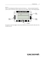
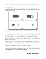
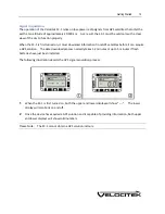
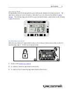
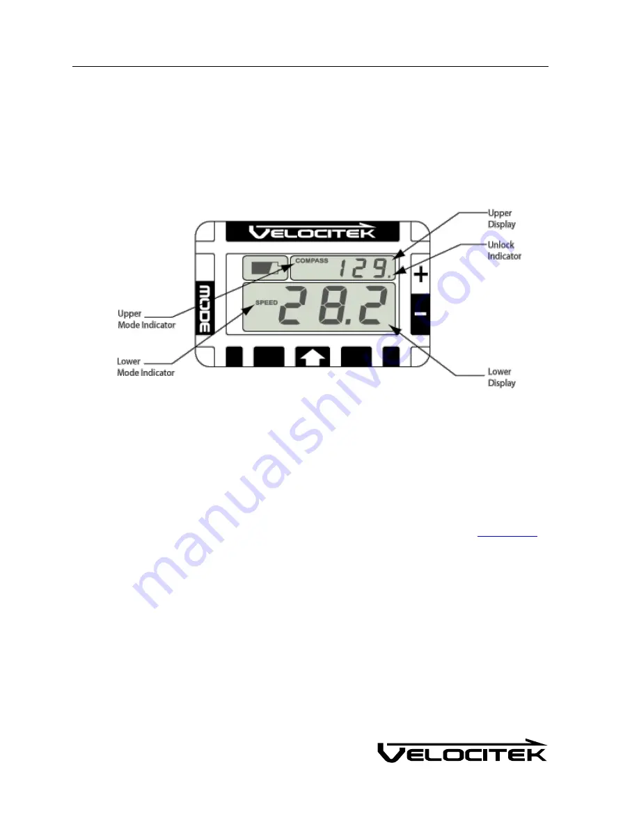
The following diagram shows the SC-1's two main display areas:
The upper and lower displays can both be used to display speed, heading, tactical heading, VMG, start
line proximity or timer information. The information shown on each display is made clear by a mode
indicator immediately to the left of the numerical display area. There is no “TIMER” indicator on the
upper display. Timer mode on the upper display is indicated simply by the presence of a colon between
the minutes and seconds. Additionally there is no start line proximity mode indicator in both upper and
lower display. No mode indicators will be displayed in either screen when the device is in start line
mode. Tactical compass mode is indicated by presence of both "COMPASS" and "VMG" indicators.
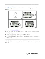
The first decimal point on the upper display is used as an unlock indicator if any of the
lock features
are
enabled. The indicator is not displayed if all lock features are disabled.
Summary of Contents for SC-1
Page 1: ...SC 1 Reference Manual Firmware Version 2 4F Full Functionality...
Page 40: ...Installing Control Center 37 3 Click Next...
Page 43: ...Installing Control Center 40 6 Select I accept click Next...
Page 44: ...Installing Control Center 41 7 Select Typical click Next...
Page 48: ...Installing Control Center 45 12 Enter User Name and Company Name Click Next...
Page 49: ...Installing Control Center 46 13 Select Typical click Next...
Page 50: ...Installing Control Center 47 14 Click Next 15 Click Continue Anyway...
Page 52: ...Installing Control Center 49 17 If prompted restart your computer Select Yes click Next...
Page 66: ...Using Control Center 63 3 Name the file and click on the Save button to complete the process...
Page 81: ...Index 78 W Wind Direction in Tactical Compass Mode 20 Wind Direction in VMG Mode 24...


