105
107774-02- 4/18
XIII. Operation
(continued)
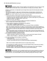
Table 13.2: Frost Protection
Device
Started
Start
Temperatures
Stop
Temperatures
Boiler Pump
Outside Air < 0°F (-18°C)
Supply Water < 45°F (7.2°C)
Outside Air > 4°F (-16°C)
Supply Water > 50°F (10°C)
Boiler
Supply Water < 38°F (3.3°C) Supply Water > 50°F (10°C)
D. Multiple Boiler Control Sequencer
This boiler may be used as a slave in a multiple
boiler system where the other boilers employ
the same control. Consult factory for additional
information on doing this.
4. External Limit
An external limit control can be installed on the
low voltage terminal strip. Be sure to remove the
jumper when adding an external limit control to
the system. If the external limit opens, the boiler
will shut down and an open limit indication and
error code are provided. If the limit installed is a
manual reset type, it will need to be reset before
the boiler will operate.
5. Boiler Mounted Limit Devices
The control monitors individual limit devices:
External Limit, Thermal Fuse, Sump Switch and
Boiler Water Flow Switch. If any of these limits
open the boiler will shut down and an open limit
indication is provided. Additionally, the control
monitors an air proving switch. During the boiler
start sequence the control requires the air proving
switch to be in the “open” position before the
blower starts and in the “closed” position after
the blower starts. If the air proving switch is not
in the required position the start sequence is
halted or the boiler is shut down and the open
limit indication is provided. The air proving switch
is only required to be closed during pre-purge.
It is normal for the air proving switch to be open
during run mode.
6. Stack High Limit
The Control monitors the flue gas temperature
sensor located in the vent connector. If the
flue temperature exceeds 194°F (90°C), the
control begins to reduce the maximum blower
speed. If the flue temperature exceeds 204°F
(96°C), a forced boiler recycle results. If the flue
temperature exceeds 214°F (101°C), the control
activates a manual reset Hard Lockout.
7. Ignition Failure
The Control monitors ignition using a burner
mounted flame sensor. In the event of an ignition
failure, the control retries 5 times and then goes
into soft lockout for one hour.
8. Central Heating System Frost Protection
When enabled, Frost Protection starts the boiler
and system pump and fires the boiler when low
outside air and low supply water temperatures
are sensed. The Control provides the following
control action when frost protection is enabled:
CAUTION The Control helps provide
freeze protection for the boiler water. Boiler
flue gas condensate drain is not protected from
freezing. Since the Control only controls the
system and boiler circulators individual zones
are not protected. It is recommended that
the boiler be installed in a location that is not
exposed to freezing temperatures.
Summary of Contents for K2WTC-135
Page 81: ...81 107774 02 4 18 X Domestic Hot Water Piping continued Figure 10 1 Domestic Hot Water Piping...
Page 89: ...89 107774 02 4 18 XI Wiring continued...
Page 90: ...90 107774 02 4 18 Figure 11 8 Internal Wiring Connections Diagram XI Wiring continued...
Page 101: ...101 107774 02 4 18 Lighting and Operating Instructions XII Start Up and Checkout continued...
Page 142: ...142 107774 02 4 18 XVI Repair Parts continued...
Page 145: ...145 107774 02 4 18 XVI Repair Parts continued...
Page 148: ...148 107774 02 4 18 XVI Repair Parts continued...
Page 150: ...150 107774 02 4 18 XVI Repair Parts continued...
Page 152: ...152 107774 02 4 18 XVI Repair Parts continued 120 121 122 123 124 125 126 127...
Page 159: ...159 107774 02 4 18 SERVICE RECORD DATE SERVICE PERFORMED...

