136
106309-03 - 4/19
10. Press “Adjust” button on Boiler Type screen.
11. Use the ↓ ↑ arrows to select the correct size
and altitude of your boiler. Press the
button
to enter your selection. See Figure 55.
12. Press “Enter” button until display stops
blinking. Press “Next” and repeat until
“Completed” is displayed.
13. Press “
” to exit.
Start-up Instructions for Natural Gas or LP
1. Confirm Phantom X boiler size, type and
installed altitude prior to startup.
2. PHNTM399C or PHNTM500C LP conversion
only: Adjust throttle screw to preliminary
setting per Table S1.
3. Start boiler as described in boiler Installation
manual and lock boiler in high fire (See
Section IX. Start-up). If boiler does not light,
turn throttle screw in ¼ turn increments in a
counterclockwise direction until boiler fires. Do
not stop here, follow Steps 4-7.
4. Verify CO
2
is within range shown in Table S2
and CO air free is less than 200 ppm. If CO
2
and CO air free are within these limits, move
to Step 6 and check fan speed at high fire
operation only.
5. If CO
2
is outside the window outlined in Table
S2, adjust throttle screw such that the CO
2
falls
in this range while boiler is locked manually
in high fire. Turning throttle screw counter-
clockwise increases the CO
2
, while clockwise
rotation leans the mixture, reducing the CO
2
.
Once CO
2
is within the limits in Table S2,
check CO air free again to ensure it is below
200 ppm. If CO air free is above 200 ppm turn
throttle screw clockwise in ¼ increments until
CO air free is below 200 ppm, while ensuring
CO
2
remains in the range specified in Table S2.
If CO air free
is still above 200 ppm, reduce fan
speed in 100 rpm increments until CO air free
is less than 200 ppm.
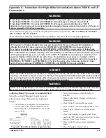
WARNING
Asphyxiation Hazard. Offset screw is adjusted
at the factory. DO NOT touch the offset screw if
measured low fire CO
2
is within limits specified
in Table S2.
Appendix A - Instructions for High Altitude Installations Above 2000 ft. and LP
Conversions
(continued)
6. Lock boiler in low fire (see Section IX. System
Start-up). Verify CO
2
is within range shown in
Table S2 and CO air free is less than 200 ppm.
7. If low CO2 is too high, decrease CO2 by
turning offset screw counter-clockwise in less
than 1/8 turn increments and checking the CO
2
and CO air free after each adjustment. If boiler
is equipped with 2 gas valves, offset screw
adjustments must be done to both gas valves
equally and simultaneously. See Figure 49 for
location of offset screw. Verify CO air free is
less than 200 ppm.
8. If low fire CO
2
is too low, increase CO
2
by
turning offset screw clockwise in less than
1/8 turn increments and checking the CO
2
and
CO air free after each adjustment. If boiler
is equipped with 2 gas valves, offset screw
adjustments must be done to both gas valves
equally and simultaneously. See Figure 49 for
location of offset screw. Verify CO air free is
less than 200 ppm.
9. Start boiler five times at the above settings
to ensure boiler lights off without delay and
without noise. Check CO
2
and CO air free to
ensure that the CO
2
is within the range specified
in Table S2 and CO air free is below 200 ppm.
Be sure to replace the screw cap in the vent
adapter when combustion testing is complete.
10. Verify that the gas inlet pressure is between
the following limits with all gas appliances
(including the converted boiler) both on and
off:
• Natural Gas: 4.0 - 14.0 inches w.c.
• LP Gas: 8.0 - 14.0 inches w.c.
If inlet pressure is not within limits, adjust
before performing high altitude setup
procedure.
11. Return boiler to Automatic Mode. Press
“Auto”.
Summary of Contents for Phantom-X PHNTM399C
Page 49: ...49 106309 03 4 19 VI Water Piping and Trim continued Figure 28 Near Boiler Piping Heating Only...
Page 63: ...63 106309 03 4 19 VIII Electrical continued Figure 40 Ladder Diagram...
Page 64: ...64 106309 03 4 19 VIII Electrical continued Figure 41 Wiring Connections Diagram 2...
Page 73: ...73 106309 03 4 19 IX System Start up continued Figure 47 Operating Instructions...
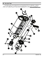
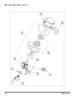
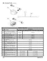
Page 124: ...124 106309 03 4 19 XIII Service Parts continued...
Page 130: ...130 106309 03 4 19 XIII Service Parts continued...
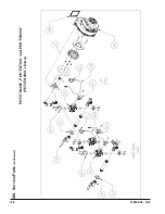
Page 133: ...133 106309 03 4 19 XIII Service Parts continued 10A 10B 10C 10D 10G...
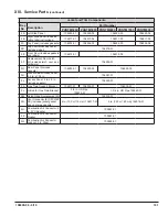
Page 139: ...139 106309 03 4 19...

